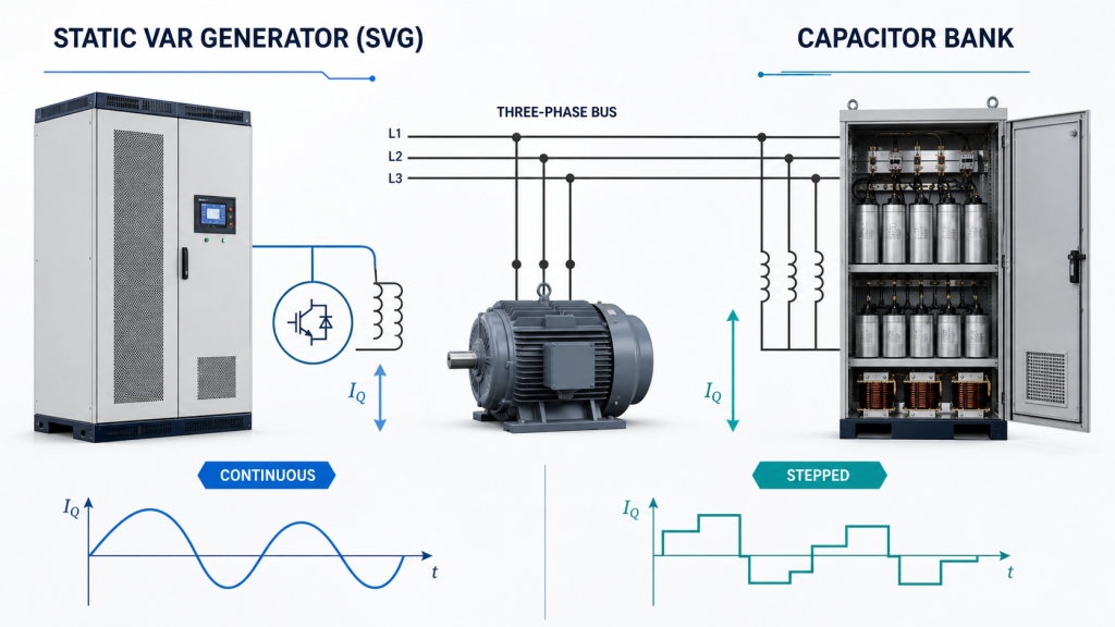
A Static Var Generator (SVG) is usually the better choice when reactive power changes quickly, phase imbalance is present, or precise power factor control is required. A capacitor bank is often more economical for stable inductive loads with low harmonic distortion. The correct choice depends on the load profile, harmonic environment, response-time target, available space and lifecycle cost—not only the initial purchase price.
Shanghai Elumotive Technology recommends measuring the electrical system before selection. A plant with steady motors may perform well with a properly engineered capacitor bank, while cranes, welding machines, elevators, rolling mills and rapidly changing production lines often need dynamic SVG compensation.
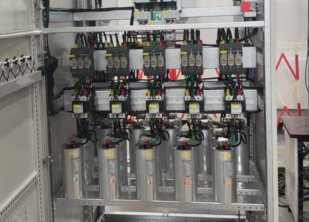
A capacitor bank supplies capacitive reactive power to offset the inductive reactive power consumed by motors, transformers and other inductive equipment. In an automatic power factor correction panel, a controller switches capacitor steps on or off through contactors or thyristors.
Capacitor banks are mature, efficient and cost-effective. They work best when:
In systems containing substantial harmonic current, ordinary capacitors may be overloaded or may interact with the network inductance. Detuned reactors are commonly added to reduce resonance risk, but their tuning and rating must be engineered for the actual system.
A Static Var Generator, also called an SVG and often described as a low-voltage STATCOM, uses power electronics to measure load current and inject the required compensating current. It can provide capacitive or inductive reactive power continuously instead of switching fixed capacitor steps.
An SVG is particularly useful when the load changes rapidly. It can follow fluctuating reactive power, correct overcompensation and undercompensation, and—depending on the equipment design—support three-phase imbalance correction.
An SVG is not the same as an Active Harmonic Filter (AHF). The SVG primarily compensates reactive power, while an AHF primarily reduces harmonic current. Read Elumotive’s AHF vs SVG comparison when both low power factor and harmonics are present.
| Selection factor | Static Var Generator (SVG) | Capacitor bank |
| Compensation method | Continuously variable electronic current | Fixed kvar steps switched on/off |
| Response | Typically millisecond-level; confirm model data | Seconds with contactors; faster with thyristor switching |
| Load profile | Rapidly changing or unstable loads | Stable or slowly changing loads |
| Power factor control | Precise, smooth correction | Limited by step size |
| Overcompensation | Can absorb or supply reactive power within rating | Requires correct control and step sizing |
| Harmonic environment | Does not rely on capacitor resonance | Requires harmonic and resonance assessment |
| Phase imbalance | May compensate by phase, depending on topology | Conventional three-phase banks have limited capability |
| Maintenance | No routine capacitor-step replacement, but cooling and electronics need inspection | Contactors, fuses and capacitors require periodic checks |
| Footprint | Often compact for dynamic compensation | Can become large with reactors and multiple steps |
| Initial cost | Usually higher | Usually lower for stable applications |
| Best fit | Cranes, welders, rolling mills, elevators, variable production loads | Steady motors, pumps, fans and stable plant loads |
The key difference is not simply “electronic equipment versus capacitors.” It is how the two solutions match the load.
A capacitor bank may be divided into steps such as 25, 50 or 100 kvar. If the system needs 63 kvar at a given moment, the controller must choose an available combination. This creates a correction band and switching delay. Frequent load changes can also produce frequent switching and component wear.
An SVG adjusts output continuously within its rated capacity. If the required compensation changes from 20 kvar to 63 kvar, the output can follow the change without waiting for a fixed step combination. This makes the SVG effective for loads whose current and power factor vary from cycle to cycle or second to second.
Power factor correction must not be selected from the monthly utility bill alone. Nonlinear loads such as Variable Frequency Drives (VFDs), UPS systems, rectifiers and EV chargers can inject harmonic current.
Capacitors change the impedance of the electrical network. If the capacitor bank and upstream inductance create a resonant condition near a dominant harmonic order, current and voltage distortion may be amplified. Symptoms can include capacitor overheating, fuse operation, reactor noise or repeated component failure.
Detuned capacitor banks use series reactors to shift the resonant frequency away from common harmonic orders. They remain a valid solution when correctly designed. However, a harmonic survey should confirm THDi, THDv and the individual harmonic spectrum before the bank is specified.
An SVG avoids capacitor-step resonance as its primary compensation mechanism, but it is not automatically a harmonic filter. If harmonic current itself is the main problem, evaluate an Active Harmonic Filter or a coordinated AHF + SVG solution.
| Application | Typical condition | Preferred starting point | Engineering note |
| Pump or fan station | Stable motor loading | Capacitor bank | Check VFD penetration and detuning need |
| Commercial building | Predictable daily load profile | Capacitor bank or hybrid | Avoid excessive step size at light load |
| Crane or hoist | Fast, regenerative duty cycles | SVG | Check bidirectional reactive demand and imbalance |
| Welding line | Rapid fluctuations and imbalance | SVG | Measure per-phase current and voltage flicker |
| Steel rolling mill | Large, fast load changes | SVG or STATCOM study | Medium-voltage system study may be required |
| Solar plant | Inverter and grid-code reactive control | SVG, subject to plant study | Confirm PCC voltage and utility requirements |
| Plant with high VFD content | Low PF plus harmonic current | SVG + AHF or engineered hybrid | Do not assume one device solves both problems |
| Stable large motor load | Consistent inductive kvar | Detuned capacitor bank | Verify harmonics and switching frequency |
Assume an operating load of 600 kW has a measured power factor of 0.78 and the target is 0.95. A first estimate of required reactive compensation is:
Qc = P × (tan φ1 − tan φ2)
where P is active power, φ1 corresponds to the existing power factor and φ2 corresponds to the target. Using approximate values:
This does not mean a 300 kvar device should be ordered immediately. Engineers must review minimum and maximum load, short-term peaks, phase imbalance, transformer loading, harmonic spectrum, voltage and future expansion. If the 284 kvar demand remains steady, a stepped detuned bank may be economical. If it rapidly varies from near zero to 284 kvar, an SVG or hybrid solution may deliver better control.
A capacitor bank can be the best engineering and commercial choice when:
“Older technology” does not mean unsuitable technology. A well-designed capacitor bank remains effective in many plants. The risk comes from installing a generic bank without system measurements or a resonance assessment.
An SVG is normally preferred when:
For medium-voltage networks, the terms SVG and STATCOM may refer to larger systems with project-specific transformers, cooling, protection and control. Selection should be based on a system study rather than a simple low-voltage kvar calculation.
Yes. A hybrid system can use a capacitor bank for stable base reactive power and an SVG for fast residual compensation. This can reduce the electronic converter rating while preserving dynamic performance.
For example, a plant with a steady 300 kvar base demand and a rapidly changing additional 0–150 kvar demand might use a properly detuned capacitor bank for the base portion and an SVG for the variable portion. The control strategy must prevent interaction and overcompensation. CT location, controller logic and switching thresholds should be reviewed as one system.
Prepare the following information before choosing an SVG or capacitor bank:
No. An SVG provides faster and more precise compensation, but a capacitor bank can be more economical for stable loads. The better solution is the one that matches the measured reactive power profile and harmonic conditions.
Its primary function is reactive power compensation. Some multifunction products may provide limited harmonic functions, but an Active Harmonic Filter should be evaluated when harmonic current reduction is the main requirement.
Yes, but the system must be checked for harmonics and resonance. Detuned reactors may be necessary. Capacitors should not be connected directly at a VFD output.
SVG systems commonly operate at millisecond-level response, but the exact response time depends on the model, control algorithm and measurement method. Confirm the manufacturer’s rated performance for the project.
Within its design and rating, an SVG can typically supply or absorb reactive current, helping correct both lagging and leading conditions. Confirm the operating range for the selected product.
Send the single-line diagram, voltage, transformer data, load trend, power factor, kW/kvar, THDi/THDv, harmonic spectrum and information about existing capacitor banks. Measurement files are more useful than one meter screenshot.
Choose a capacitor bank for stable, predictable reactive power demand when harmonic and resonance risks are properly controlled. Choose a Static Var Generator for fast-changing, unbalanced or precision-sensitive loads. Consider a hybrid system when there is a large steady base demand plus a smaller dynamic component.
Shanghai Elumotive Technology supplies Static Var Generator (SVG/STATCOM), Active Harmonic Filter (AHF/APF) and coordinated power quality solutions. Explore Elumotive products, review the power quality solutions, or contact Elumotive with your measurements for a project-specific evaluation.