For industrial plants, data centers, commercial buildings, EV charging stations and renewable energy projects, harmonic current is no longer a small side issue. Modern power systems use more power electronics than before: variable frequency drives, UPS systems, rectifiers, inverters, chargers, LED drivers and welding equipment. These devices improve control and efficiency, but they can also draw distorted current from the electrical network.
Shanghai Elumotive Technology provides Active Harmonic Filter, Active Power Filter, Static Var Generator, SVG, STATCOM and complete power quality solutions for these applications. This article explains how an AHF works, when it is used, and what information engineers should collect before selecting one.
In an ideal AC power system, voltage and current waveforms are close to sine waves. Many traditional linear loads, such as simple resistive heaters, draw current in a relatively smooth waveform.
Nonlinear loads behave differently. A variable frequency drive or rectifier often draws current in short pulses instead of a smooth sine wave. These pulses contain harmonic components at frequencies above the fundamental frequency. In a 50 Hz system, for example, the 5th harmonic is 250 Hz and the 7th harmonic is 350 Hz.
When many nonlinear loads are connected to the same transformer or feeder, harmonic current can accumulate. This may lead to:
An Active Harmonic Filter is normally connected in parallel with the electrical distribution system. Current transformers measure the load current or source current at the selected compensation point. The AHF controller analyzes the measured waveform and separates the fundamental current from the harmonic current.
After identifying the harmonic component, the AHF uses power electronics to inject a compensation current with the opposite harmonic waveform. This injected current cancels a large part of the harmonic current seen by the upstream transformer or utility side.
The basic process is:
1. Measure current through CTs.
2. Detect harmonic components in real time.
3. Calculate the compensation current required.
4. Inject opposite harmonic current into the system.
5. Continuously adjust compensation as the load changes.
This dynamic response is one reason AHF is useful for facilities where load conditions change throughout the day.
In many power quality projects, AHF, APF and Active Power Filter refer to the same general technology. The naming depends on supplier preference, regional terminology and product documentation.
Elumotive uses the terms Active Harmonic Filter and Active Power Filter to describe power electronics equipment designed mainly for harmonic current compensation. Some products may also support limited reactive power or load balancing functions, but the primary selection purpose is harmonic mitigation.
An Active Harmonic Filter is mainly selected when the site has measured harmonic current problems. It is not chosen only because a transformer is large or because a plant has many motors. The decision should be based on power quality data.
| Site Condition | Why AHF Is Considered | Engineering Note |
| High THDi at main panel | Nonlinear loads are distorting current | Confirm individual harmonic orders before sizing |
| Many VFDs on one transformer | Drive rectifiers can create 5th, 7th, 11th and 13th harmonics | Check load profile during normal production |
| UPS or rectifier loads | Front-end power electronics can create harmonic current | Data centers and industrial DC systems often need review |
| Capacitor bank problems | Harmonics may create resonance or overheating | Review capacitor/reactor design before adding compensation |
| Utility or project harmonic requirement | Harmonic limits may apply at PCC | IEEE 519 is commonly referenced in many projects |
| Sensitive equipment alarms | Distorted current and voltage may affect nearby equipment | Measure both THDi and THDv |
Both active and passive filters can reduce harmonics, but they work differently.
A passive harmonic filter is built from capacitors, reactors and resistors. It is tuned to specific harmonic frequencies and can work well in stable systems. However, passive filters require careful engineering because system impedance, capacitor banks and load changes can affect tuning and resonance risk.
An Active Harmonic Filter uses power electronics and real-time control. It can compensate multiple harmonic orders and adapt to changing load conditions. For plants with mixed nonlinear loads, changing production schedules or future expansion plans, AHF often provides more flexibility.
| Filter Type | Best Fit | Strength | Limitation |
| Line reactor | Small VFD groups or basic current smoothing | Simple and low cost | Limited harmonic reduction |
| Passive harmonic filter | Stable loads with known harmonic spectrum | Efficient targeted filtering | Needs resonance and tuning review |
| Active Harmonic Filter | Variable nonlinear loads and changing production | Dynamic multi-order compensation | Requires correct CT location and sizing |
| AHF + SVG | Sites with both high THDi and low power factor | Harmonic mitigation plus reactive compensation | Needs integrated power quality design |
An AHF can be installed at different points depending on the problem.
For a plant-wide harmonic issue, the AHF may be installed at the main low-voltage distribution panel. This helps reduce harmonic current seen by the transformer and upstream network.
For a specific production line, motor control center or feeder, the AHF may be installed closer to the nonlinear load group. This can reduce equipment size and target the actual harmonic source.
For large or complex systems, engineers may combine centralized and local compensation. The right location depends on measurement data, electrical layout, CT installation feasibility, expansion plans and the target compensation point.
AHF sizing should be based on measured harmonic current, not only on transformer capacity. Before selecting equipment, collect:
Assume a feeder carries 800 A during normal production. A power quality analyzer measures current THDi at 30%.
Estimated harmonic current:
800 A x 30% = 240 A
If the project target is to reduce THDi close to 5%, the remaining harmonic current target would be:
800 A x 5% = 40 A
The simplified compensation demand is:
240 A – 40 A = 200 A
In this example, engineers may initially consider an AHF around 200 A, with margin depending on load fluctuation, harmonic spectrum, CT location and future expansion. Final sizing should always be confirmed with actual measurement data and project conditions.
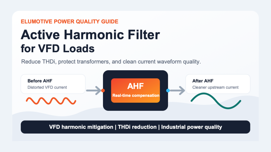
An Active Harmonic Filter can improve true power factor by reducing harmonic distortion. However, if the main issue is displacement power factor or rapidly changing reactive power, a Static Var Generator (SVG) may be the better primary solution.
Many industrial sites have both problems:
In this case, an AHF and SVG can be used together. The AHF reduces harmonic current, while the SVG provides dynamic reactive power compensation and helps improve power factor.
For a detailed comparison, see Elumotive’s article: Active Harmonic Filter vs Static Var Generator: What Is the Difference?
Active Harmonic Filters are commonly used in:
For VFD-specific guidance, read: Active Harmonic Filter for VFD Loads: How to Reduce THDi in Industrial Power Systems
Shanghai Elumotive Technology helps customers evaluate power quality projects by reviewing site data such as voltage level, transformer capacity, load current, THDi, THDv, harmonic spectrum, power factor, existing capacitor banks and installation conditions.
Elumotive can recommend whether the project should use Active Harmonic Filter, Static Var Generator, SVG, STATCOM, capacitor/reactor solutions or a combined power quality system.
The main purpose of an Active Harmonic Filter is to reduce harmonic current generated by nonlinear loads. It helps lower THDi and reduce harmonic stress on transformers, cables, switchgear, capacitor banks and sensitive equipment.
In many projects, AHF and APF refer to the same type of power quality equipment. AHF means Active Harmonic Filter, while APF means Active Power Filter. Both terms are commonly used for active harmonic current compensation.
No. An AHF mainly solves harmonic distortion, while a Static Var Generator mainly solves reactive power and dynamic power factor problems. If a site has both high THDi and low power factor, both AHF and SVG may be needed.
An AHF can be installed at the main low-voltage panel, a feeder panel, a motor control center or near a nonlinear load group. The correct location depends on where harmonic current must be reduced and where CTs can measure the target current.
An AHF can help reduce harmonic current at the selected compensation point and may support IEEE 519 project targets. Final compliance depends on measurement location, system short-circuit ratio, harmonic spectrum, load profile and project-specific limits.
Send system voltage, transformer capacity, load current, THDi, THDv, individual harmonic spectrum, power factor, existing capacitor bank details, installation photos and the target standard or utility requirement. Elumotive can use this information for an initial power quality solution review.
An Active Harmonic Filter is a dynamic power quality device used to reduce harmonic current in modern electrical systems. It is especially useful where VFDs, UPS systems, rectifiers, EV chargers and other nonlinear loads create high THDi.
The best AHF selection starts with measurement data. Engineers should check current distortion, voltage distortion, harmonic spectrum, load profile, capacitor bank conditions and the required harmonic target before choosing equipment.
If your project has high harmonic current or unexplained transformer, cable, capacitor or power quality problems, contact Elumotive for a project evaluation.
CTA: Send your voltage level, transformer capacity, load current, THDi/THDv report and application details to Elumotive for an initial Active Harmonic Filter selection review.
Contact: sales@elumotive.com
Website: https://www.elumotive.com