
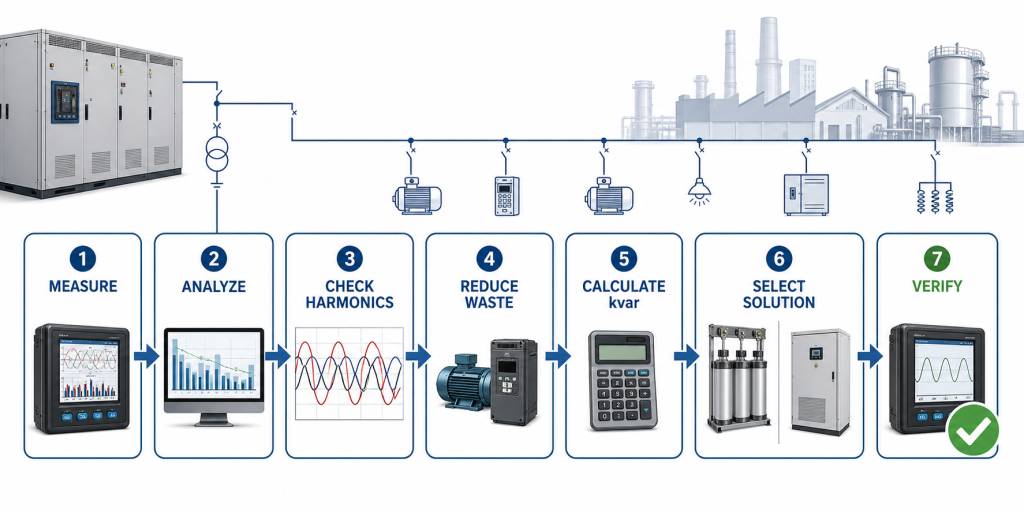
To improve power factor in an industrial plant, first measure active power, reactive power, power factor and harmonics across the plant’s real operating cycle. Then reduce avoidable idle or lightly loaded equipment and select the right compensation method: capacitor banks for stable inductive demand, a Static Var Generator (SVG) for rapidly changing or unbalanced demand, or a hybrid solution for mixed loads. Harmonic conditions must be checked before adding capacitors.
Power factor correction is not only a utility-bill exercise. A properly engineered solution can reduce reactive current, release transformer and cable capacity, limit voltage drop and improve system efficiency. An incorrectly selected solution can cause overcompensation, switching instability or harmonic resonance.
Power factor is the ratio of real power, measured in kilowatts (kW), to apparent power, measured in kilovolt-amperes (kVA):
Power factor = kW / kVA
Real power performs useful work. Reactive power, measured in kvar, supports magnetic fields in motors, transformers and other inductive equipment. Apparent power represents the combined electrical demand placed on the supply system.
A power factor of 0.80 means that substantially more current is required to deliver the same useful kW than at 0.95, assuming the same voltage and load. Low power factor increases current in transformers, cables and switchgear. However, “true power factor” can also be affected by waveform distortion, so displacement power factor and harmonics should both be reviewed.
Common causes include:
Before specifying equipment, identify whether the problem is steady inductive reactive power, fast-changing reactive power, harmonic distortion, phase imbalance, or a combination.
| Step | Action | Key output | Common mistake to avoid |
| 1 | Confirm the target | Utility requirement and engineering target | Assuming 1.00 is always necessary |
| 2 | Measure the full operating cycle | kW, kvar, PF, current and load trends | Using one meter snapshot |
| 3 | Check harmonics and imbalance | THDi, THDv and harmonic spectrum | Adding capacitors before a harmonic review |
| 4 | Remove avoidable causes | Better equipment scheduling and loading | Compensating idle equipment indefinitely |
| 5 | Calculate kvar requirement | Initial compensation range | Sizing only from transformer kVA |
| 6 | Select the technology | Capacitor bank, SVG or hybrid | Choosing only by initial price |
| 7 | Verify after installation | PF trend, current, temperature and alarms | Checking only at peak load |
Check the utility tariff, grid-code requirements and the plant’s internal engineering goals. Many facilities target a stable value such as 0.95 or higher, but the correct target varies. Forcing the system to 1.00 can create leading power factor during light-load periods if control steps are too large or measurement is incorrect.
Define:
A portable power quality analyzer or permanent meter should record at least one representative production cycle. A plant with weekly batch processes may require several days of data. Record:
Trend data reveals whether reactive demand is a steady 250 kvar, repeatedly cycles between 50 and 300 kvar, or changes too quickly for contactor-switched capacitor steps.
Some improvements require operating changes rather than new compensation equipment:
These measures may reduce the required kvar rating and improve the economics of the final solution.
For a predominantly sinusoidal system, an initial kvar estimate can use:
Qc = P × (tan φ1 − tan φ2)
where:
A production line operates at 800 kW with a power factor of 0.82. The target is 0.96.
This calculation is a starting point. It does not capture rapid changes, harmonic distortion, imbalance, voltage variation or future expansion. Select the final rating from measured trends and the equipment’s actual operating range.
An automatic capacitor bank switches fixed kvar steps to match relatively stable reactive demand. It is often the lowest-cost choice for motors, pumps, fans and steady process loads.
Use detuned reactors when the harmonic study requires them. Step sizes should be small enough to prevent hunting and leading power factor at light load. Check capacitor voltage stress, ambient temperature and ventilation.
A Static Var Generator (SVG) uses power electronics to provide continuously variable reactive current. It is appropriate for cranes, welders, rolling mills, elevators and production processes where load changes are too fast or too granular for fixed capacitor steps.
An SVG can also address leading and lagging demand within its rating and may support phase-by-phase compensation. See the detailed Static Var Generator vs capacitor bank guide after the first article is published.
A hybrid design uses capacitors for the steady base kvar and an SVG for the dynamic remainder. This can balance capital cost and control performance. The controls, CT location, switching thresholds and harmonic environment must be coordinated.
An Active Harmonic Filter (AHF) primarily cancels harmonic current. It is not a direct substitute for an SVG when reactive power is the dominant issue. Some AHF equipment can provide reactive current within its converter capacity, but simultaneous harmonic and reactive requirements must be included in sizing.
If the plant uses many nonlinear loads, read THDi vs THDv and what an Active Harmonic Filter does.
| Site condition | Recommended starting solution | Why |
| Stable inductive load, low harmonics | Automatic capacitor bank | Economical stepped compensation |
| Stable load with material harmonics | Detuned capacitor bank after study | Reduces resonance risk when correctly designed |
| Rapidly changing reactive demand | SVG | Continuous, fast response |
| Strong phase imbalance | SVG with suitable topology | Phase-by-phase compensation capability |
| Stable base load plus dynamic peaks | Hybrid capacitor bank + SVG | Capacitors cover base; SVG follows changes |
| High THDi is the primary issue | AHF | Targets harmonic current |
| Low PF and high harmonic current | Coordinated SVG/AHF or multifunction study | Separate the reactive and harmonic requirements |
Power factor correction can be centralized at the main distribution board, distributed by feeder, or installed near individual loads.
CT position and polarity are critical. The controller or SVG must measure the intended load current without unintentionally including its own compensation current. Generator and bus-coupler operating modes should also be considered.
After installation, test at minimum, normal and peak production conditions. Verify:
Continue periodic inspection. Capacitors age, contactors wear, cooling paths collect dust and plant loads change over time.
A 1,000 kVA transformer does not automatically need a fixed percentage of kvar compensation. Actual load and reactive demand may be far lower or highly variable.
Installing plain capacitors in a harmonic-rich network can amplify distortion or damage components. Measure THDi, THDv and individual harmonics first.
Large capacitor steps may alternate between undercompensation and overcompensation. Step sequence should match the smallest meaningful change in reactive demand.
Harmonic distortion can reduce true power factor even when displacement power factor is close to one. A capacitor bank does not remove harmonic current.
A system that performs well at peak production may become leading overnight or during shutdown periods. The correction system must follow the complete operating range.
The required value depends on utility rules and system goals. Many plants aim for at least 0.95, but the correct target and acceptable leading limit should be confirmed locally.
Power factor correction does not directly reduce the useful kW required by a process. It can reduce current and I²R losses in cables and transformers, release capacity and avoid utility reactive-power charges where applicable.
It can compensate upstream inductive reactive demand, but it does not remove VFD harmonic current. A harmonic and resonance study is required, and capacitors must never be connected to the VFD output unless explicitly designed for that purpose.
Use an SVG when reactive demand changes quickly, phase imbalance matters, fixed capacitor steps cannot hold the target, or leading and lagging compensation are both required.
An AHF can improve true power factor by reducing harmonic current, and some models can also supply reactive current. The converter must be sized for the combined requirement; an SVG remains the dedicated solution for dynamic reactive compensation.
Send the single-line diagram, voltage and frequency, transformer data, kW/kvar/PF trends, current by phase, THDi/THDv, harmonic spectrum, load list, existing capacitor details and the required target at the selected point.
The reliable way to improve industrial power factor is to measure first, remove avoidable causes, calculate the actual kvar range, match the technology to the load dynamics, and verify performance across the full operating cycle. Capacitor banks suit many stable loads; SVG systems suit rapid or precise compensation; hybrid systems can combine their strengths. Harmonic current may require a coordinated AHF solution.
Shanghai Elumotive Technology provides Static Var Generator (SVG/STATCOM), Active Harmonic Filter (AHF/APF) and engineered reactive power compensation solutions. Review Elumotive products and solutions, or contact Elumotive with your measurement data for a project evaluation.