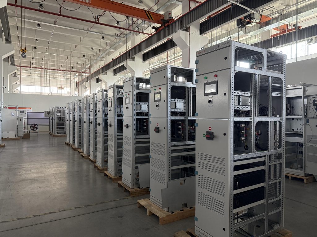
A Static Var Generator for cranes supplies and absorbs reactive current dynamically as hoists, trolley drives, winches, and other cyclic loads accelerate, lift, lower, and regenerate. Unlike a step-switched capacitor bank, an SVG can respond continuously to a changing reactive-power demand without waiting for a capacitor step to switch. This makes it useful for cranes and other fast-changing loads where low power factor, rapid kvar swings, or voltage fluctuation occurs over short duty cycles. An SVG does not automatically solve harmonic distortion, deep voltage dips, or regenerative energy; the final design should be based on time-series measurements, drive topology, source impedance, and the project’s performance target.
Cranes are not constant-speed, constant-torque loads. A typical duty cycle can include motor starting, acceleration, lifting, travel, braking, lowering, standby, and repeated reversal. Each state can change the active and reactive current seen by the supply.
The reactive-power demand may be especially variable when the installation includes:
The result is often a power factor that changes significantly during a work cycle rather than one stable monthly average. A fixed capacitor bank may correct one operating point but overcompensate another. Switching steps can also be too coarse or too slow for short events.
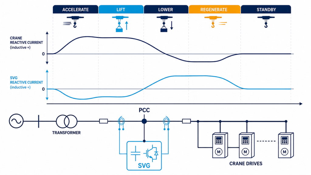
A Static Var Generator, also called an SVG or an advanced static var generator (ASVG) in some product ranges, uses a power-electronic converter to generate or absorb controlled reactive current. Current transformers measure the relevant source or load current, and the controller regulates the converter to move the system toward the selected power-factor, reactive-power, or voltage-support target.
The SVG is connected in parallel with the load. It does not need to be placed in series with a crane motor, and it does not replace the drive’s own control system. Its effect depends on the selected measurement point, CT polarity, phase sequence, controller settings, available current capacity, and the impedance between the SVG and the load.
For cranes, the practical value is dynamic control: the SVG can follow the changing kvar demand instead of applying a fixed correction step. For a basic comparison with capacitor banks, see Static Var Generator vs Capacitor Bank.
The first selection question should be “what is changing, and what must be improved?” Reactive current, harmonic current, voltage dips, flicker, and regenerative energy are related but different engineering problems.
| Technology | Main function | Suitable crane condition | Key limitation |
| Automatic capacitor bank | Step-based reactive-power correction | Stable motor load with predictable kvar demand | Step size and switching speed may not follow short duty cycles; resonance risk requires review |
| Detuned capacitor bank | Reactive correction with resonance-risk control | More stable loads where harmonics and capacitor interaction are managed | Still step-based; does not dynamically cancel harmonic current |
| Static Var Generator | Fast, continuous reactive-current compensation | Hoists, cranes, and cyclic loads with changing power factor | Current rating is finite; does not by itself remove all harmonics or deep voltage dips |
| Active Harmonic Filter | Dynamic harmonic-current compensation | Crane drives with significant measured THDi or multiple nonlinear loads | Must be sized from harmonic-current spectrum and CT arrangement |
| SVG + AHF or hybrid system | Reactive and harmonic compensation together | Shared crane bus with both rapid kvar swings and distortion | Requires coordinated control priorities, space, and commissioning |
| STATCOM / MV STATCOM | Dynamic reactive and voltage support at medium or high voltage | Large MV crane networks or severe system-level voltage variation | Higher project complexity; requires a complete system study |
An SVG should not be specified simply because a crane is present. If the dominant issue is harmonic current from VFD front ends, an Active Harmonic Filter vs Static Var Generator comparison is a better starting point. If the system is medium voltage and flicker or voltage support is the primary concern, review the MV STATCOM application for electric arc furnaces and rolling mills for the distinction between LV SVG and MV STATCOM projects.
Collect measurements before assuming that a low power factor is caused by one crane. A useful survey records the following at the PCC and, where helpful, at the crane feeder:
Power factor can appear low because of reactive current, distortion current, or both. An SVG can address the reactive-current component when correctly configured, but it should not be presented as a universal harmonic filter. The industrial power-factor improvement guide explains why measurement over time is more useful than a single meter reading.
Decide whether the SVG will support one crane feeder, a group of cranes, or the main low-voltage bus. Draw the transformer, PCC, feeder, crane drives, CT locations, capacitor banks, and proposed SVG connection on one single-line diagram.
Record enough time to include lifting, lowering, travel, braking, idle, and simultaneous crane operation. If the crane schedule changes by shift, capture more than one representative period. Short events should not be hidden by a long averaging interval.
Identify the maximum inductive kvar, the minimum kvar, and any leading or regenerative operating states. The SVG must have enough current capacity for the selected target at the relevant voltage and temperature. A single peak that lasts a few cycles may require a different control and rating discussion than a sustained demand.
Possible targets include a power-factor threshold, a kvar limit, a voltage-support mode, or a combined strategy. If the SVG is paired with an AHF, document whether reactive current or harmonic current has priority when the converter reaches its current limit.
Review transformer capacity, short-circuit level, cable length, voltage tolerance, generator operation, grounding, and protective-device coordination. Long crane feeders can have enough impedance for a local compensation device to improve the feeder voltage response, but this must be verified rather than assumed.
Allow for planned crane additions, higher production rates, temperature derating, and measurement uncertainty. Record the reason for each margin. Avoid sizing directly from motor nameplate kW or crane lifting capacity because neither represents the actual time-varying kvar demand.
Consider two cranes sharing a 400 V bus. A time-series survey shows that the combined inductive reactive demand reaches 180 kvar during simultaneous lifting and acceleration, falls to 40 kvar during travel, and occasionally becomes slightly leading during a braking transition. The project target is to keep the bus power factor above the agreed threshold without switching a large capacitor step during each event.
A first-pass SVG review would consider:
The 180 kvar observation is not automatically a final product size. The engineering team should convert the measured kvar envelope into the manufacturer’s current-rating basis at the site voltage, apply documented margin, and validate the response with the actual crane operating sequence.
CT placement determines what the SVG sees and compensates. Source-side CTs may be appropriate when the objective is to regulate the upstream bus, while load-side arrangements may be selected for a dedicated crane feeder. The correct arrangement depends on the control scheme and manufacturer instructions.
Before commissioning, verify:
An SVG cannot correct a wiring or CT polarity error through software settings alone. The commissioning team should compare measured voltage, kvar, and power factor before and after enablement at the same operating states.
Fast crane movements can create voltage variation, but the cause must be separated from ordinary reactive-power demand. An SVG may support voltage and reactive current within its rating, yet a severe voltage dip caused by a weak source, a long feeder, or a large motor event may require network reinforcement, a drive-control review, or a higher-voltage dynamic-support solution.
Lowering and braking can also return active energy to the DC link or supply. Reactive-power compensation does not consume that regenerated active energy. The project may need a braking resistor, regenerative drive, energy-storage interface, or a coordinated drive solution. Do not describe an SVG as a regenerative-energy device unless the specific product architecture includes that function.
An SVG and an AHF can complement each other when measurements show both major reactive-power swings and harmonic current. The SVG handles dynamic leading or lagging reactive current, while the AHF targets measured harmonic-current components. A combined system needs:
Shanghai Elumotive Technology can review crane duty-cycle records, feeder measurements, drive data, and expansion plans to determine whether an SVG, AHF, hybrid system, or MV STATCOM study is appropriate.
No. An SVG is most useful when the measured issue is dynamic reactive power or changing power factor. A stable load may be served by a suitable capacitor solution, while a harmonic or voltage-dip problem may require another technology.
Sometimes, but not automatically. An SVG provides continuous dynamic correction and may be preferable where the kvar demand changes quickly. A capacitor bank can remain economical for stable base-load reactive power, and a hybrid design may use both.
Not by default. An SVG primarily supplies or absorbs reactive current. Harmonic mitigation should be based on measured harmonic current and may require an Active Harmonic Filter, a passive filter, a low-harmonic drive, or a coordinated hybrid system.
It may improve voltage support associated with reactive-current changes within its rating, but it cannot guarantee correction of a deep dip caused by source capacity, feeder impedance, protection operation, or an active-power event. A system study is required.
Use time-series kvar and power-factor measurements, operating scenarios, voltage, source impedance, temperature, future growth, and the required target. Crane lifting capacity or motor kW alone is not a reliable sizing basis.
Yes, when the CT boundaries, control priorities, protection, and current limits are coordinated. The design should test their combined response during simultaneous crane operation and transitions.
Prepare the crane single-line diagram, drive and motor data, transformer and feeder information, time-series kW/kvar/power-factor records, harmonic spectra, duty-cycle notes, and future expansion plan. Contact Elumotive for an engineering review and a recommendation for an SVG, AHF, hybrid compensation system, or MV STATCOM study.
Editorial note: This article is educational and does not replace a site power-quality study, equipment manufacturer instructions, or applicable utility and project requirements.