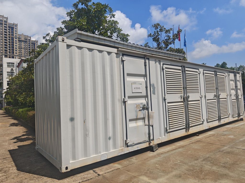
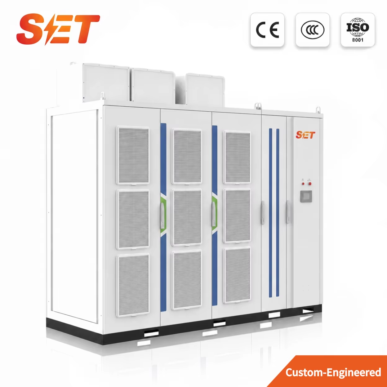
Electric arc furnaces (EAFs) and rolling mills are among the most demanding loads connected to a medium-voltage network. Their rapidly changing current, reactive-power demand and nonlinear operation can create voltage flicker, low power factor, harmonic distortion, transformer stress and unstable bus voltage. An MV STATCOM for electric arc furnace applications addresses these problems by injecting or absorbing reactive current in milliseconds, helping the plant maintain stable voltage through each melting and rolling cycle.
This engineering guide explains how a medium-voltage STATCOM—also called a medium-voltage static var generator (MV SVG)—supports steel plants, how it differs from SVC and capacitor-bank solutions, and what data should be collected before selecting the correct rating.
An EAF is a highly variable and nonlinear load. During bore-down, melting, refining and electrode movement, the arc length and furnace impedance change continuously. These variations produce rapid reactive-current swings and voltage fluctuations at the point of common coupling (PCC). A rolling mill adds another rapidly cycling load: large drives accelerate, decelerate and reverse while stands enter or leave the process.
The result is not one isolated symptom but a group of interacting power-quality problems. If the plant only corrects average power factor, voltage flicker and dynamic voltage variation may remain.
| Power-quality issue | Typical source in a steel plant | Operational consequence | What should be measured |
|---|---|---|---|
| Voltage flicker | Rapid EAF arc-power and reactive-power changes | Visible lamp flicker, utility complaints, unstable auxiliary loads | Pst, Plt and voltage variation at the PCC |
| Low or fluctuating power factor | Furnace transformer, EAF and large mill drives | Higher current, demand penalties and reduced network capacity | kW, kvar, PF and Q(t) over the full production cycle |
| Voltage sag and bus instability | High current during furnace bore-down and mill acceleration | Drive trips, contactor dropout and reduced production continuity | Minimum RMS voltage and short-circuit strength |
| Harmonic distortion | Nonlinear arc, rectifiers and variable-speed drives | Transformer heating, resonance risk and nuisance trips | THDi, THDv and individual harmonic spectrum |
| Three-phase unbalance | Asymmetric arc conditions and electrode movement | Negative-sequence current and additional motor heating | Negative-sequence voltage/current and phase imbalance |
A STATCOM is a shunt-connected, converter-based dynamic reactive-power compensator. It measures the grid and load conditions, calculates the required compensating current, and controls its voltage-source converter to inject capacitive current or absorb inductive current. Because the output is controlled electronically rather than by switching fixed capacitor steps, compensation can follow fast EAF and rolling-mill load changes.
For an arc-furnace installation, the control objective is normally broader than “raise the power factor.” A properly engineered system may be configured to:
DIgSILENT’s published EAF simulation example applies a STATCOM to compensate furnace-current variations and calculates flicker according to IEC 61000-4-15 methodology. In that illustrative model, Plt decreases from 1.4282 without compensation to 0.6741 with STATCOM compensation—a calculated reduction of approximately 52.8%. Actual plant performance depends on short-circuit capacity, furnace duty cycle, measurement location, control tuning and STATCOM rating, so this result should be treated as an engineering example rather than a universal guarantee.
| Illustrative DIgSILENT simulation metric | Without STATCOM | With STATCOM | Calculated improvement |
|---|---|---|---|
| Average short-term flicker Pst | 1.4278 | 0.6732 | 52.8% reduction |
| Long-term flicker Plt | 1.4282 | 0.6741 | 52.8% reduction |
| Assessment method | Flickermeter calculation based on IEC 61000-4-15 in the cited simulation model | ||
Capacitor banks, thyristor-based SVC systems and converter-based STATCOM systems can all provide reactive-power compensation, but they behave differently during rapid voltage and load changes. The most appropriate solution depends on the target performance, network strength and total project economics.
| Criterion | MV STATCOM / MV SVG | SVC | Switched capacitor bank |
|---|---|---|---|
| Response to fast load changes | Millisecond-level continuous current control | Fast thyristor-controlled response | Stepwise; generally slower |
| Reactive output at depressed voltage | Current-controlled output supports better low-voltage performance | Reactive output decreases approximately with voltage squared | Reactive output decreases approximately with voltage squared |
| Flicker-mitigation capability | Strong for rapidly varying EAF and mill loads when correctly sized and tuned | Established solution; performance depends on design and network conditions | Usually insufficient as the sole fast-flicker solution |
| Physical footprint | Compact modular converter system | Requires reactors, capacitors and harmonic-filter equipment | Relatively simple but needs step switching and protection |
| Harmonic considerations | Converter and control design require coordinated harmonic study | Passive filter branches are commonly part of the solution | Resonance and inrush must be assessed |
| Best fit | Fast dynamic compensation, weak grids, space limits and stringent flicker targets | Large conventional installations with suitable footprint and filter design | Stable, slowly changing reactive demand |
For a broader explanation of step-switched compensation versus converter-based compensation, see our guide: Static Var Generator vs Capacitor Bank.
STATCOM sizing should be based on time-synchronized measurement data, not only the furnace-transformer MVA rating. Two furnaces with the same transformer rating can require different compensation because their short-circuit strength, operating cycles, electrode control and utility limits are different.
Start with measurable targets: PCC power factor, maximum voltage variation, utility flicker limits, harmonic limits, permitted negative-sequence level and production-trip reduction. The IEC 61000-4-15 flickermeter standard defines functional and design specifications for flicker measurement. Local grid codes may set additional planning or emission limits.
Measurements should cover bore-down, melting, refining, tapping, idle intervals and representative rolling schedules. High-resolution trends are needed because ten-minute averages can hide the peak dynamic demand that drives flicker and voltage sag.
Analyze Q(t), voltage variation and the correlation between reactive current and flicker. The STATCOM should be able to follow the required dynamic range without operating continuously at its current limit. Engineering margin must account for furnace variability, future production increases and network changes.
A weak grid generally needs more dynamic voltage support than a strong grid. The study should include grid short-circuit MVA, X/R ratio, transformer impedance, cable/reactor impedance and the proposed connection bus. The PCC defined by the utility may differ from the STATCOM connection bus.
For major steel projects, a time-domain model should reproduce the measured EAF or rolling-mill load. The study then tests candidate STATCOM ratings, controller bandwidth, current limits, transformer/reactor parameters and interaction with passive filters. Harmonic and flicker results should be assessed both before and after compensation.
| Input required for selection | Minimum information | Why it matters |
|---|---|---|
| Network data | System voltage, frequency, short-circuit MVA, X/R ratio and utility limits | Defines grid strength and voltage sensitivity |
| Transformer data | MVA, impedance, vector group, tap range and secondary voltage | Determines fault level and converter interface |
| Load profile | Time-series MW, Mvar, current, voltage and production stage | Defines dynamic compensation range and duty cycle |
| Flicker data | Pst, Plt, voltage-change waveform and measurement location | Sets the flicker-control target |
| Harmonic data | THDi, THDv and individual harmonic currents/voltages | Identifies filter and resonance requirements |
| Site conditions | Indoor/outdoor, altitude, temperature, dust, cooling water and available footprint | Determines enclosure, cooling and derating |
| Expansion plan | Future furnace capacity, rolling stands or parallel production lines | Prevents undersizing and supports modular expansion |
Medium-voltage systems commonly use cascaded converter cells or another modular multilevel arrangement to achieve the required voltage. Module redundancy, bypass design, cell replacement time and spare-parts strategy should be reviewed during technical evaluation.
Steel plants can combine high ambient temperature, conductive dust, vibration and restricted maintenance access. Cooling capacity, filter maintenance, pressurization, IP rating and altitude derating must match the site. A nominal Mvar value without environmental derating can be misleading.
The STATCOM controller should coordinate with the furnace-transformer tap changer, electrode regulator, existing capacitor banks, passive harmonic filters and plant protection. Control priorities may change by operating stage—for example, voltage stabilization during bore-down and power-factor optimization during steadier refining periods.
Review converter overcurrent protection, DC-link protection, cooling alarms, cell bypass, isolation, grounding, anti-condensation heating and communication-failure behavior. For a production-critical furnace, maintainability and partial-capacity operation can be as important as the rated response time.
In industrial power-quality projects, the terms are often used for closely related voltage-source-converter systems that provide dynamic reactive-current compensation. Project terminology varies by vendor, voltage level and grid application, so the specification should define functionality rather than rely only on the name.
No single claim should replace a harmonic study. A STATCOM primarily provides dynamic reactive-current and voltage support. Depending on topology and control, it may support selected harmonic objectives, but passive filters, active filters or a coordinated hybrid design may still be required.
Yes, in many projects the capacitor bank supplies steady-state kvar while the STATCOM handles rapid dynamic variation. The combined system must be checked for resonance, switching logic and control interaction.
The most useful starting package is a synchronized time-series file containing three-phase voltage and current, MW, Mvar, PF, Pst/Plt and harmonic spectra across complete furnace or rolling cycles, together with grid short-circuit data and transformer parameters.
Shanghai Elumotive Technology develops custom medium-voltage SVG and STATCOM systems for electric arc furnaces, rolling mills, mining, renewable-energy plants and utility substations. Share your single-line diagram, transformer data, PCC measurements and operating cycle with our engineering team for a preliminary compensation proposal.
Email: sales@elumotive.com
Tel: +86 182 0194 9796
Location: Shanghai, China
Request an MV STATCOM assessment or browse our medium-voltage power-quality products.