An Active Harmonic Filter for UPS loads measures nonlinear load current and injects an opposing compensation current into the electrical bus. It can reduce harmonic current drawn by six-pulse UPS rectifiers, improve the current waveform at the selected compensation point, and help limit voltage distortion caused by the interaction of harmonic current with system impedance. Correct selection is not based on UPS kVA alone: engineers should measure harmonic spectra and operating states, define the target at the point of common coupling (PCC), and check generator, bypass, capacitor-bank, CT, and redundancy conditions before sizing the filter.
A conventional rectifier does not draw current as a smooth sine wave. Its input diodes or thyristors conduct during parts of each voltage cycle, creating a pulsed current waveform. A six-pulse rectifier typically produces characteristic harmonic orders around the 5th, 7th, 11th, and 13th, although the actual spectrum depends on topology, input impedance, loading, DC-link design, and any built-in chokes or filters.
These harmonic currents can cause:
Modern double-conversion UPS systems with active-front-end rectifiers can have much lower input distortion than older six-pulse designs. Therefore, the phrase “UPS load” is not enough to select a mitigation device. The actual UPS model, input stage, loading, operating mode, and site measurements matter.
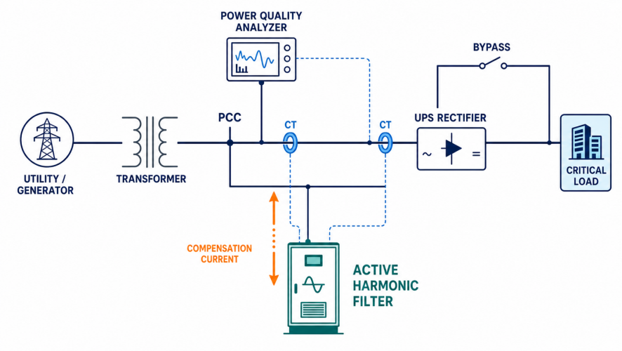
The useful measurement point depends on the engineering objective. If the goal is utility or facility-level compliance, measurements normally focus on the agreed PCC. If the goal is to protect a transformer, generator, or critical bus, an additional local measurement point may be required.
Do not confuse equipment input THDi with site-level current distortion. A UPS datasheet value is measured under stated test conditions, while a facility contains multiple loads, changing demand, source impedance, and operating modes. For an explanation of the main distortion metrics, see THDi vs THDv: What Is the Difference in Power Quality?.
When IEEE 519 is specified, the assessment boundary and the applicable project or utility requirements should be confirmed. Current distortion at the PCC is commonly evaluated using total demand distortion (TDD) and the short-circuit-current-to-demand-load-current ratio, not a single instantaneous UPS THDi reading.
Different measures solve different versions of the problem. The best choice depends on whether the installation is new or existing, how much the UPS loading changes, and whether compensation is needed for one load or a shared bus.
| Option | Best suited to | Main strength | Main limitation |
| AC line reactor or DC choke | Basic reduction at one rectifier | Simple and robust | Usually provides limited harmonic reduction |
| Passive harmonic filter | Stable, known load spectrum | Efficient for designed harmonic orders | Performance varies with loading and system impedance; resonance must be checked |
| Low-harmonic or active-front-end UPS | New equipment selection | Harmonics addressed inside the UPS design | Replacement cost and compatibility constraints |
| Multipulse rectifier | Large, relatively stable installations | Cancels selected characteristic harmonics | Requires phase-shifting transformer and balanced loading |
| Active Harmonic Filter | Variable loads or several nonlinear loads on one bus | Dynamic, multi-order compensation | Requires correct CTs, rating, settings, and installation environment |
An AHF is especially useful when several legacy UPS or rectifier loads operate at changing percentages of rated load. It can be installed in parallel with the bus and adjusted to the selected compensation target. For a broader technology comparison, read AHF vs Passive Harmonic Filter.
Current transformers measure the load or source current. The AHF controller separates the harmonic components from the fundamental component and commands the power converter to inject compensation current with approximately opposite phase. The source then supplies a waveform closer to the desired fundamental current.
The AHF does not remove harmonics inside the UPS. It changes the current seen upstream of the selected compensation point. CT location, CT direction, phase sequence, and controller mode therefore determine which loads are compensated and what the upstream source sees.
An AHF may also provide reactive-current or imbalance compensation when the selected model supports those functions. However, its current capacity is finite. If one device is asked to compensate harmonics, reactive power, and imbalance simultaneously, the priority logic and remaining capacity must be defined. See Active Harmonic Filter vs Static Var Generator when reactive power is the main issue.
Decide whether the AHF will compensate one UPS input, a group of UPS units, or a common bus containing other nonlinear loads. Record the exact CT and AHF connection points on a single-line diagram.
Capture current, voltage, THDi, THDv, individual harmonic orders, power factor, and demand during:
Use measured RMS current by harmonic order where possible. A rough screening calculation can estimate total harmonic current from load current and THDi, but it does not replace the spectrum needed for final selection. The practical method in the Active Harmonic Filter sizing guide
Define the desired upstream spectrum or distortion target at the selected point. Avoid promising “zero harmonics.” Residual distortion depends on the filter rating, control bandwidth, source impedance, background voltage distortion, CT accuracy, wiring, and load dynamics.
Allow for future load growth, simultaneous battery charging, temperature derating, supply-voltage tolerance, and the AHF manufacturer’s current-rating method. Do not apply a generic margin without documenting what it covers.
Critical-power systems need a clear answer to what happens if one AHF module is unavailable. Modular N+1 filtering may be appropriate when harmonic mitigation is operationally important, but the required redundancy level should follow the facility risk assessment.
Assume a measured UPS group draws 600 A RMS during a representative high-load condition. The analyzer reports 32% THDi at the UPS feeder, and the project team wants to reduce the dominant harmonic current at the upstream bus. A screening estimate of the harmonic component is:
Estimated harmonic current = 600 A × 0.32 = 192 A
This result is only a first-pass value. The engineer should next review individual harmonic currents, diversity among parallel UPS modules, the target at the PCC, generator mode, future growth, and site derating. Depending on those checks, a modular AHF arrangement around the required compensation current may be considered. Final selection must use measured spectrum data and manufacturer validation rather than rounding 192 A to a product size automatically.
Generators usually present higher source impedance than the utility supply. The same harmonic current can therefore create more voltage distortion during generator operation. Load steps, AVR response, UPS input-current ramping, and AHF commissioning settings must be coordinated.
Confirm that the proposed AHF can synchronize and operate correctly over the generator’s expected voltage and frequency range. Commissioning should include generator tests at safe, representative load conditions. An AHF should not be treated as a substitute for generator and UPS compatibility studies.
Shanghai Elumotive Technology can review single-line diagrams, analyzer records, UPS topology, transformer and generator data, and expansion plans before proposing an Active Harmonic Filter configuration. The objective is a solution tied to measured site conditions rather than UPS nameplate capacity alone.
No. Many modern UPS systems have low-distortion active-front-end inputs, while older or lightly loaded six-pulse UPS systems may produce much more harmonic current. Measure the system and review the UPS topology before selecting mitigation.
Yes, when the units are downstream of the measurement and compensation point and the AHF has sufficient capacity and control performance. The design must account for diversity, parallel-module states, and future load growth.
No. UPS kVA is useful context, but final sizing should use measured or reliably modeled harmonic current by order, operating scenarios, the required target, and installation derating.
It can reduce the harmonic current that produces voltage distortion across system impedance, which may reduce THDv. It cannot directly guarantee a specific THDv where background voltage distortion or other sources dominate.
It can, provided the filter is compatible with the generator voltage and frequency range and the whole system is correctly coordinated. Generator mode should be included in the design review and commissioning tests.
CTs should be placed according to whether the control scheme uses source-side or load-side sensing and which loads must be compensated. Polarity, phase mapping, and the single-line diagram must match the AHF manufacturer’s instructions.
For a reliable proposal, prepare the single-line diagram, UPS and rectifier models, voltage, measured current and harmonic spectra, generator information, operating modes, and future expansion plan. Contact Elumotive for an engineering review and an AHF selection recommendation for your UPS or rectifier system.