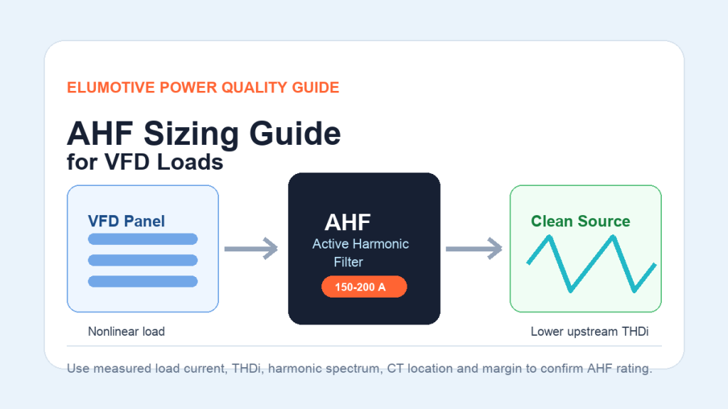
An Active Harmonic Filter for VFD loads should be sized from measured harmonic current, not only from transformer capacity or motor power. The practical starting point is to measure load current, current total harmonic distortion (THDi) and individual harmonic orders at the target compensation point. Engineers then estimate the harmonic current that must be compensated, add margin for load changes and future expansion, and confirm the final AHF rating with CT location, voltage level, cooling, panel space and the required harmonic target such as IEEE 519.
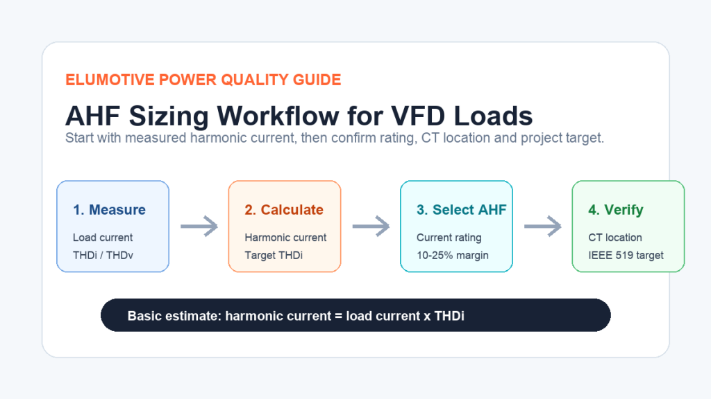
Image placement: use a sizing workflow graphic after the introduction. Recommended visual: measurement -> harmonic current calculation -> AHF rating -> CT location -> verification.
Variable frequency drives improve motor control and energy efficiency, but their rectifier front ends can draw nonlinear current from the electrical network. In many industrial plants, VFD groups become one of the main sources of 5th, 7th, 11th and 13th harmonic current. If the AHF is undersized, THDi may remain too high. If it is oversized without measurement data, the project may spend budget without solving the real power quality problem.
Shanghai Elumotive Technology provides Active Harmonic Filter, Active Power Filter, Static Var Generator, SVG, STATCOM and complete power quality solutions for industrial projects. This guide explains the practical AHF sizing logic engineers can use before sending project data for final selection.
A VFD converts AC power to DC and then back to controlled AC output for the motor. This power conversion is useful, but the input current is often not a clean sine wave. A typical 6-pulse drive can create strong lower-order harmonics, especially the 5th and 7th harmonics.
When many VFDs are connected to one transformer, motor control center or production line, harmonic current can accumulate. This may cause:
For more background on VFD harmonic problems, read: Active Harmonic Filter for VFD Loads: How to Reduce THDi in Industrial Power Systems
Before calculating AHF size, decide where harmonic current should be reduced. This is also where the current transformers should measure the target current.
Common compensation points include:
| Compensation Point | When to Use It | Sizing Note |
| Main low-voltage switchboard | Plant-wide VFD harmonic issue | Larger AHF size, broader upstream improvement |
| Motor control center | Several VFDs grouped in one MCC | Good balance between cost and targeted compensation |
| Specific feeder | One production line creates most harmonics | Easier to match AHF rating to the real harmonic source |
| Near large VFD load | One major drive dominates distortion | Local solution, but check upstream system impact |
If the CTs are installed at the wrong point, the AHF may compensate the wrong current. This is one of the most common reasons a harmonic mitigation project performs poorly.
AHF sizing should start with power quality measurement under normal production conditions. A short measurement during idle load may underestimate the required compensation current.
Collect these values:
If possible, measure across different operating states: startup, normal production, peak production and low-load conditions.
For the difference between THDi and THDv, see: THDi vs THDv: What Is the Difference in Power Quality?
A simple first estimate is:
Harmonic current = load current x THDi
For example, if a VFD feeder carries 600 A and measured THDi is 32%, the estimated harmonic current is:
600 A x 32% = 192 A
This does not automatically mean the AHF rating must be exactly 192 A. The final rating depends on the target THDi, harmonic spectrum, load variation, CT location and engineering margin. But this calculation gives a useful starting point.
The AHF does not always need to remove all harmonic current. The target is usually to reduce harmonic distortion to an acceptable level at the selected point.
Example:
In this simplified case, engineers may initially consider an AHF around 160 A to 200 A, depending on available module ratings and margin requirements.
The table below gives a simplified early-stage estimate. It is not a replacement for measured harmonic spectrum review, but it helps engineers understand the selection logic.
| Load Current at Compensation Point | Measured THDi | Estimated Harmonic Current | Typical Initial AHF Review Range |
| 300 A | 25% | 75 A | 75-100 A |
| 500 A | 30% | 150 A | 150-200 A |
| 800 A | 30% | 240 A | 240-300 A |
| 1000 A | 35% | 350 A | 350-450 A |
| 1500 A | 25% | 375 A | 400-500 A |
The final selection should consider whether the load is stable or variable. A production line with frequent changes may need more margin than a stable process load.
THDi is useful, but it is not enough by itself. Two sites can both show 30% THDi but have different harmonic spectra.
For VFD loads, engineers commonly review:
An Active Harmonic Filter can compensate multiple harmonic orders dynamically, but the actual spectrum helps confirm required current rating and control strategy.
AHF sizing should include practical margin. Common reasons include:
A common early-stage approach is to add 10-25% margin after estimating the required compensation current. For fast-growing plants, future expansion may justify a modular AHF cabinet with space for additional modules.
Many VFD-heavy plants also have power factor correction capacitor banks. Harmonic current and capacitor banks can interact with system impedance and create resonance. This may cause capacitor overheating, fuse failure or abnormal voltage distortion.
Before adding an AHF, review:
If the site has both harmonic current and reactive power problems, Elumotive may recommend a combined AHF + SVG solution.
Correct CT installation is critical. Even a properly sized AHF can perform badly if CT polarity, phase sequence or measurement location is wrong.
Check the following before commissioning:
| CT Item | Why It Matters |
| CT installed at target compensation point | The AHF must measure the current it is expected to compensate |
| Correct phase sequence | Incorrect phase mapping can reduce compensation performance |
| Correct polarity | Reversed CT direction can cause wrong compensation output |
| Suitable CT ratio and accuracy | Poor measurement affects control precision |
| CT wiring separated from interference | Noise can affect measured current signals |
Assume an industrial VFD panel has the following data:
Estimated harmonic current at normal production:
720 A x 28% = 201.6 A
If the target remaining harmonic current is roughly:
720 A x 8% = 57.6 A
Simplified compensation demand:
201.6 A – 57.6 A = 144 A
After considering peak operation and margin, engineers may review a 150 A to 200 A AHF option. If future VFD expansion is expected, a modular cabinet with spare capacity may be more practical than a fixed one-time rating.
Avoid these mistakes:
For a basic explanation of AHF operation, read: What Is an Active Harmonic Filter and How Does It Work?
An Active Harmonic Filter is mainly selected for harmonic current compensation. If the site also has low power factor, voltage fluctuation or fast-changing reactive power, a Static Var Generator may be needed.
Some projects need:
Explore related pages:
Transformer capacity can help define system scale, but it should not be the only sizing basis. AHF rating should be based mainly on measured load current, THDi, harmonic spectrum and the target compensation point.
The target depends on the project requirement, utility request and measurement point. Many projects reference IEEE 519 at the point of common coupling, but the exact limit depends on system conditions. Internal panel targets may be different from PCC targets.
It depends on measured THDi and target THDi. If the feeder has 20% harmonic current, the estimated harmonic current is about 200 A. If THDi is higher or future expansion is expected, a larger or modular AHF may be needed.
If the goal is plant-wide upstream improvement, the main panel may be suitable. If one VFD group is the main harmonic source, installation near that feeder or MCC may be more efficient. Measurement data should guide the location.
An AHF can reduce harmonic current, but capacitor bank failures may also involve resonance, detuned reactor design, switching problems or aging. The capacitor bank should be reviewed before selecting the final solution.
Send voltage level, transformer capacity, load current, THDi, THDv, harmonic spectrum, power factor, capacitor bank details, single-line diagram if available, installation photos and the target standard or utility requirement.
Active Harmonic Filter sizing for VFD loads should start with real measurement data. The most useful inputs are load current, THDi, individual harmonic spectrum, target compensation point and required harmonic limit. After estimating harmonic current, engineers should add practical margin and confirm CT location, capacitor bank conditions and future expansion.
If your plant has high THDi from VFD loads, send Elumotive your power quality report and application details. Elumotive can review whether the project needs an Active Harmonic Filter, Active Power Filter, Static Var Generator, SVG, STATCOM or a combined power quality solution.
CTA: Contact Elumotive for an initial AHF sizing review. Send voltage level, transformer capacity, load current, THDi/THDv report, harmonic spectrum and installation photos.
Contact: sales@elumotive.com
Website: https://www.elumotive.com