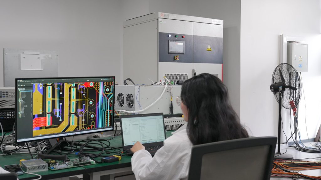
Variable frequency drives are widely used in industrial power systems. They help motors run more efficiently, control process speed, reduce mechanical stress and support automation. But VFDs are also one of the most common sources of harmonic current in low-voltage and medium-voltage distribution networks.
A modular active harmonic filter can be installed near VFD groups, MCC feeders or the main low-voltage panel to reduce harmonic current.
When several VFDs operate on the same transformer or feeder, the current waveform can become heavily distorted. This distortion is often measured as current total harmonic distortion, or THDi. High THDi may cause transformer heating, cable losses, nuisance tripping, capacitor bank problems and poor power quality for nearby equipment.
An active harmonic filter is designed to solve this problem dynamically. It measures harmonic current in real time and injects an opposite compensation current, helping the upstream current waveform become cleaner.
This article explains why VFDs create harmonics, when an active harmonic filter is needed, and what data engineers should collect before selecting an AHF.
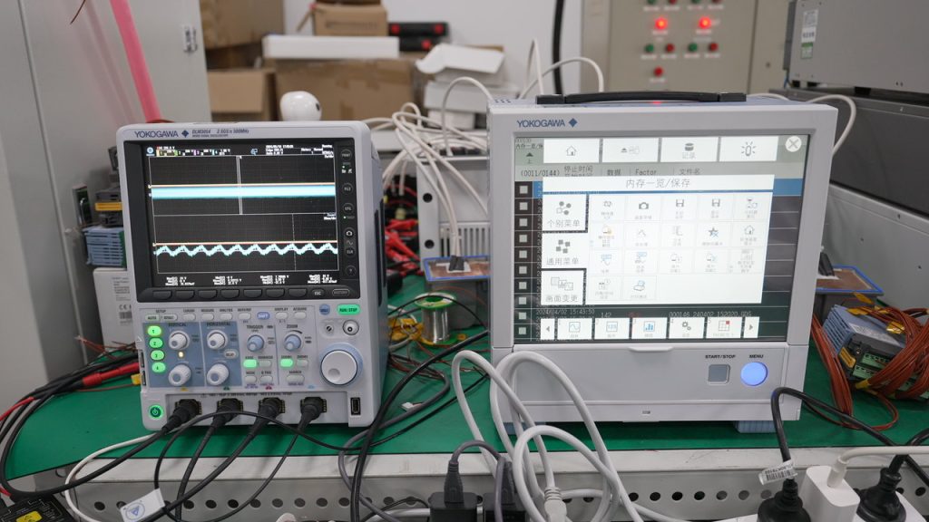
A standard variable frequency drive converts incoming AC power into DC and then uses power electronics to create a controlled output for the motor. The input rectifier stage does not draw current as a smooth sine wave. Instead, it draws current in pulses.
These current pulses create harmonic components at frequencies above the fundamental frequency. In many three-phase systems, common harmonic orders include the 5th, 7th, 11th and 13th harmonics. The exact harmonic profile depends on drive topology, load condition, system impedance and installation design.
The important point is simple:
VFDs are nonlinear loads. Nonlinear loads can distort current. When many nonlinear loads are connected together, harmonic current can accumulate.
High harmonic distortion is not always obvious at first. A plant may continue operating, but electrical equipment gradually runs hotter or less reliably. Typical symptoms include:
These symptoms do not always prove that harmonics are the only issue, but they are strong signs that a power quality measurement should be performed.
An active harmonic filter is a power electronics device installed in parallel with the electrical system. It continuously monitors load current through current transformers and calculates the harmonic current component.
The AHF then injects a compensation current with the opposite harmonic waveform. The goal is to cancel harmonic current at the selected measurement point, often the main low-voltage panel, motor control center or point of common coupling.
Unlike passive filters, an active harmonic filter is not tuned only to one fixed frequency. It can respond dynamically to changing VFD load conditions. This makes it useful in plants where motor speed, production load and operating schedule change throughout the day.
Engineers often compare active harmonic filters with line reactors and passive harmonic filters.
A line reactor is simple and cost-effective. It can reduce current peaks and improve the input current waveform to some extent. However, it may not be enough when a plant has strict harmonic targets or many VFDs on the same transformer.
A passive harmonic filter is designed around specific harmonic frequencies. It can be effective in stable systems, but it needs careful engineering because resonance with capacitor banks or system impedance can create risk.
An active harmonic filter is more flexible. It can compensate multiple harmonic orders and adapt to changing load conditions. For facilities with variable production profiles, mixed nonlinear loads or future expansion plans, AHF is often the more practical solution.
| Solution | Best Use | Main Strength | Limitation |
| Line reactor | Small or moderate VFD groups | Simple installation and lower cost | Limited THDi reduction |
| Passive harmonic filter | Stable load profile with known harmonic orders | Good targeted harmonic reduction | Needs resonance review and careful tuning |
| Active harmonic filter | Multiple VFDs with changing operating conditions | Dynamic multi-order harmonic compensation | Requires correct CT location and sizing |
| AHF + SVG | Systems with both high THDi and low power factor | Harmonic mitigation plus dynamic reactive power compensation | Higher system scope, needs integrated design |
An AHF is usually considered when measurement data shows that harmonic current is the main power quality problem.
Typical situations include:
If a plant only has a few small VFDs and harmonic levels are low, an active harmonic filter may not be necessary. The correct decision should be based on measurement data, not only equipment nameplates.
Before selecting an active harmonic filter for VFD loads, engineers should collect real operating data. A short-term power quality measurement during normal production is much more useful than guessing.
Important data points include:
This data helps determine whether the AHF should be installed at the main incoming panel, a specific feeder, or near a group of nonlinear loads.
| Measurement Item | Why It Matters for AHF Selection |
| Load current at compensation point | Determines the real current base for harmonic current calculation |
| Current THDi and harmonic spectrum | Shows how much harmonic current must be compensated |
| 5th, 7th, 11th and 13th harmonic orders | Helps confirm whether the harmonic pattern matches typical VFD behavior |
| Voltage THDv | Confirms whether current distortion is already affecting voltage quality |
| Transformer capacity and impedance | Helps evaluate heating risk and upstream power quality impact |
| Existing capacitor bank or reactor | Helps avoid resonance and wrong compensation strategy |
Assume an industrial feeder carries 600 A during normal production. A power quality analyzer measures current THDi at 32%.
A simplified estimate of harmonic current is:
600 A x 32% = about 192 A harmonic current
If the project target is to reduce THDi close to 5%, the remaining harmonic current target would be:
600 A x 5% = about 30 A
The estimated compensation demand is therefore:
192 A – 30 A = about 162 A
In this simplified case, engineers may consider an AHF around 160 A to 200 A, depending on harmonic spectrum, load fluctuation, safety margin and future expansion.
Final sizing should always be confirmed with measured data and site conditions.
The installation point affects compensation performance and cost.
For a plant-wide harmonic problem, the AHF may be installed at the main low-voltage distribution panel. This helps clean current seen by the transformer and upstream utility side.
For a specific production line or motor control center, the AHF may be installed at the feeder level. This can reduce harmonic current from a concentrated group of VFDs without oversizing the system for the whole plant.
For mixed loads, engineers may combine centralized and local compensation strategies.
An active harmonic filter can improve true power factor by reducing harmonic distortion. However, if the main issue is displacement power factor or dynamic reactive power, a Static Var Generator may be more suitable.
In many industrial systems, both problems exist together:
In this case, an AHF and SVG can be used together. The AHF reduces harmonic distortion, while the SVG improves power factor and compensates reactive power dynamically.
One common mistake is selecting an AHF only by transformer size. Transformer capacity is useful, but AHF sizing should be based on harmonic current and load profile.
Another mistake is adding capacitor banks without checking harmonics. In a harmonic-rich system, capacitors may create resonance or suffer from overheating.
A third mistake is measuring only during light load. Harmonic distortion and load current may change significantly during different production periods.
Shanghai Elumotive Technology provides active harmonic filters and power quality solutions for industrial plants, commercial buildings, data centers, renewable energy projects and EV charging infrastructure.
For VFD harmonic mitigation projects, we can help review basic electrical data, including voltage level, transformer capacity, VFD load profile, THDi, harmonic spectrum and installation conditions.
Based on the site information, Elumotive can recommend a suitable AHF configuration and help customers evaluate whether AHF alone is enough or whether a combined AHF + SVG solution is more appropriate.
VFDs are valuable for motor control and energy efficiency, but they can also create harmonic current. When many VFDs operate in the same electrical system, high THDi can affect transformers, cables, capacitor banks and sensitive equipment.
An active harmonic filter is a flexible and dynamic solution for VFD harmonic mitigation. It measures harmonic current in real time and injects compensation current to improve upstream current waveform quality.
The best selection should be based on measured data, harmonic spectrum, load profile and project targets. If you are planning a VFD-heavy industrial project, contact Elumotive with your basic site data and our team can help evaluate the right power quality solution.
Contact: sales@elumotive.com Website: https://www.elumotive.com Tel#:+8618201949796