Replacing a VFD, UPS system or charger is often treated as a like-for-like maintenance task. The voltage, nominal kW or breaker size may appear unchanged, yet the new equipment can have a different input rectifier, harmonic spectrum, partial-load behavior, reactive-power control mode, charging logic or load ramp. Those changes can affect an existing active harmonic filter (AHF), static var generator (SVG), capacitor bank, transformer, generator and protection arrangement.
Quick answer: Before energizing replacement nonlinear equipment, update the single-line diagram and collect the new input-performance data. Compare the proposed operating states with the existing baseline at the relevant bus or PCC. Review harmonic spectrum, power factor, load ramp, transformer thermal margin, capacitor-bank compatibility, AHF/SVG capacity, protection and control interfaces. Re-test at the same measurement point after controlled energization; do not rely on nominal kW or a supplier data sheet alone.
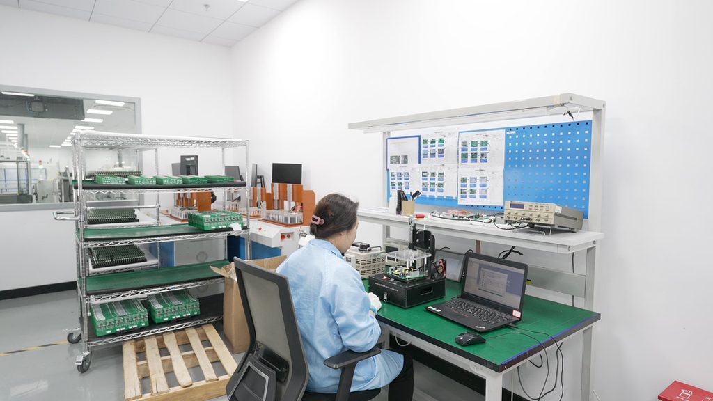
Two devices with the same output rating can present different demand to the supply. An older six-pulse VFD and a newer low-distortion drive may draw different harmonic current by order. A replacement UPS may change rectifier topology, battery-charging behavior, bypass logic or partial-load characteristics. A higher-power DC charger can include a different active front end, power-sharing method and ramp-rate limit.
The effect is not automatically negative. New equipment can reduce distortion or improve displacement power factor. The engineering issue is that the previous system assumptions may no longer be valid. Existing capacitor steps, filter settings, transformer loading calculations and protective-device coordination were often selected around the prior load behavior.
Treat a nonlinear-load replacement as a controlled system change when it affects a shared transformer, common bus, generator, capacitor bank or power-quality device.
The change-control review should identify more than the new equipment’s nominal rating.
| Change event | Electrical assumption affected | Data to request | Verification before energization |
|---|---|---|---|
| VFD replacement | Input harmonic orders, DC choke/AFE topology, motor ramp and regenerative behavior | Harmonic curve, input topology, current rating, control modes | Compare feeder spectrum, thermal load and AHF capacity |
| UPS upgrade | Rectifier behavior, battery charging, bypass and generator-mode demand | Input THDi curve, PF data, battery charging profile, bypass sequence | Test utility, battery, bypass and generator states |
| Charger power upgrade | Concurrency, ramp rate, input spectrum and power sharing | Charger schedule, operating states, input performance data | Check transformer, PCC, SVG/AHF and voltage trend |
| Added parallel equipment | Diversity, neutral current, source impedance and protection coordination | Quantity, phase allocation, simultaneous-duty assumptions | Update bus loading and fault/protection review |
| Capacitor-bank change | Resonance frequency, kvar step, switching and voltage rise | Capacitor/reactor data, control steps and settings | Review spectrum and switching behavior before closing stages |
| Firmware or control update | Current limit, compensation priority, timing or communications | Release note, approved parameter set and rollback plan | Functional test and documented baseline/post-change comparison |
A product data sheet may state rated power, voltage range and a maximum THDi at a particular load. That is not enough for a system review. Ask for the conditions behind the figure:
For large changes, obtain manufacturer curves or a representative test report. A claim such as “low THDi” should be tied to a stated operating point. Partial load may matter more than rated load if the facility spends most of its time in that range.
An existing AHF is sized for a measured or assumed harmonic-current envelope. If a load replacement changes the spectrum, the current by order or the duty cycle, the AHF may have unused margin, it may need a different enabled-order setting, or it may reach its limit in a new operating state.
An SVG should be reviewed against the revised kvar envelope and voltage range. A device that corrected a previous motor-driven load may see a different leading or lagging requirement after an upgrade. If harmonic and reactive compensation share converter current in a hybrid unit, a change in one demand can reduce the headroom available for the other.
Capacitor banks need special attention. A new nonlinear load can shift the interaction between system inductance, capacitor stages and any detuned reactor. Do not assume that a bank which operated normally with the previous equipment remains safe after the replacement. Compare voltage and current spectrum with capacitor stages on and off where site procedures permit.
A repeatable workflow reduces the chance that an upgrade creates an unexplained trip after energization.
A post-change review should capture both normal operation and transitions. Harmonic current and power factor can be evaluated over defined aggregation intervals. Voltage dips, inrush, transfer events, charger ramps or UPS bypass changes may require event recording with synchronized timestamps.
IEC 61000-4-30:2025 defines methods for measurement and interpretation of power-quality parameters in AC supply systems. When a project specifies measurement methods or instrument class, follow that method so pre- and post-change records remain comparable.
Do not use a successful no-load startup as evidence that the final system is acceptable. Include the operating states that are most likely to challenge the shared electrical system: maximum credible load, concurrent starts, battery charging, generator operation, capacitor switching and normal production transitions.
Consider a facility that replaces an existing UPS and adds cooling VFD capacity during the same shutdown. The total IT kW remains similar, so the project team initially plans to keep the existing AHF and capacitor bank unchanged.
Before energization, the team should compare the old and new UPS input topology, battery-charging profile and harmonic spectrum. It should also estimate the additional VFD current and its operating schedule. The AHF review should compare expected harmonic amperes with available compensation current under site temperature. The capacitor-bank review should check switching steps, detuned-reactor data and voltage distortion. The commissioning plan should include utility mode, bypass, battery charging and the intended cooling-load combinations.
The purpose is not to assume the upgrade will create a problem. It is to preserve evidence and identify whether the original electrical design conditions remain valid.
For related system checks, review our generator, VFD and UPS power-quality guide and harmonic-spectrum guide.
No. Low THDi at one equipment test condition does not define the aggregate site spectrum, PCC voltage distortion, partial-load behavior, concurrent operation or interaction with existing equipment.
No. AHF sizing depends on harmonic current, spectrum, duty cycle, available capacity and the required residual target—not only total kW.
Not every minor change requires the same level of analysis. The appropriate scope depends on load size, harmonic content, existing capacitor banks, source impedance, project risk and applicable requirements. A change that alters nonlinear load materially should at least trigger a documented compatibility review.
A controlled replacement protects the wider electrical system as well as the new device. Send the old and new equipment list, technical input data, current single-line diagram, existing power-quality records, compensation equipment details and proposed energization window to Elumotive for an initial change-control review.


Leave a Comment