Generator power quality with VFD and UPS loads is not settled by nameplate kilowatts. A generator can carry the required kilowatts yet deliver an unacceptable voltage waveform. VFD and UPS rectifiers draw pulsed current; those harmonic currents cross alternator and feeder impedance, creating harmonic voltage drops on the bus supplying converters and sensitive loads. The issue is therefore a source–load interaction, not merely a THD number.
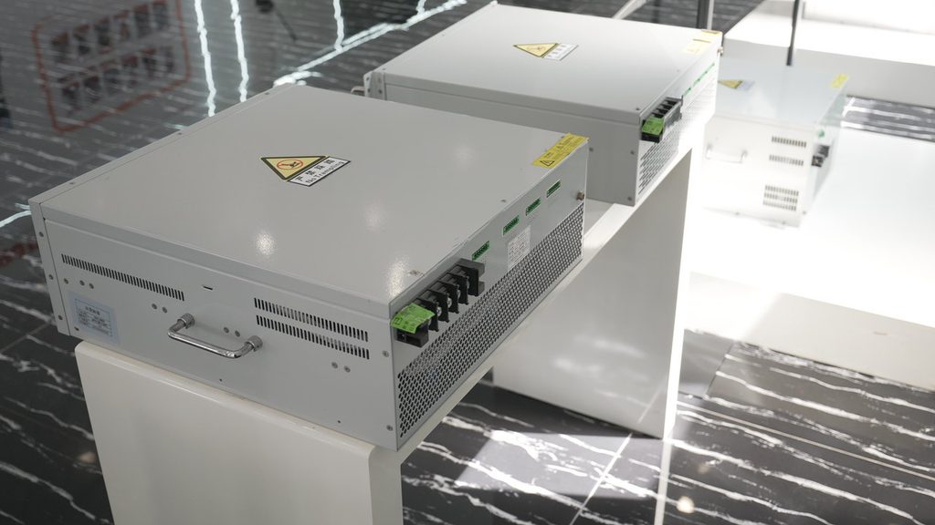
Harmonics matter more for generator power quality with VFD and UPS loads because a generator is normally a weaker source than the utility. Confirm transient capability, alternator reactance, excitation, permissible leading power factor, load acceptance, and converter generator-mode requirements. Then measure or model credible states, including UPS recharge and lightly loaded VFDs.
An active harmonic filter (AHF) can reduce selected harmonic current, but rating and control stability depend on spectrum, source impedance, topology, load variation, and location. A filter cannot replace a generator stability study, transient/load-step review, or verification of generator and converter OEM limits.
A utility network and transformer often provide high short-circuit capacity. A local generator generally has lower fault strength and higher source impedance on the same load base. Alternator reactance, stator resistance, cables, and transformers contribute, while effective impedance varies with frequency and time.
For harmonic order h, a useful screen is:
Vh ≈ Ih × Zsource,h
This is not a complete stability model. Low current THD does not guarantee low voltage distortion where source impedance is high. Published subtransient reactance, X″d, helps comparison, but use OEM data on the correct kVA and voltage base and include the distribution path. The AVR also matters: distorted sensing, commutation notches, and changing reactive demand can challenge excitation. Engine governing operates on another timescale, so generator selection cannot be reduced to steady-state kW.
A conventional six-pulse bridge often produces prominent 5th, 7th, 11th, and 13th currents. Actual magnitudes depend on loading, DC-link impedance, reactors, and source impedance; twelve-pulse and active-front-end equipment behave differently.
A UPS may reach maximum input demand while carrying load and recharging batteries. Input ramp, current limit, generator mode, and synchronization window can determine transfer success. VFDs avoid across-the-line motor inrush, but several accelerating together can create a steep real-power ramp. At light load, THDi percentage may rise while harmonic amperes fall.
Single-phase switch-mode loads may add triplen neutral current. Capacitors or tuned filters may create resonance. Inventory each converter’s front end, input components, expected spectrum, power factor, efficiency, maximum input kVA, and operating modes.
On a weak source, distorted voltage can change converter current, while the AHF, UPS, VFD, and AVR control loops respond concurrently. Possible symptoms include unstable voltage, UPS transfers, VFD alarms, alternator noise, nuisance trips, capacitor heating, or neutral current. None proves a harmonic cause: frequency excursions, bad connections, sensing errors, imbalance, or excessive load steps can look similar. Capture synchronized voltage, current, frequency, and events before choosing a remedy.
Use a power-quality analyzer rated for the installation and follow approved safety procedures. Record at the generator bus and, where practical, the nonlinear feeder and proposed filter point. Test:
Capture phase and neutral RMS values, kW, kVA, displacement and total power factor, THDv, THDi, individual harmonic magnitudes, frequency, unbalance, crest factor, and event waveforms. Trend complete operating cycles and verify analyzer wiring and CT orientation.
Capacity checks must cover steady kW/kVA, engine load acceptance, alternator heating, voltage and frequency recovery, protection, and OEM nonlinear-load guidance. More alternator kVA may reduce impedance on the load base, but does not automatically cure engine or controls limitations.
Sequence essential auxiliaries, stagger VFD acceleration, limit coincident steps, and coordinate UPS recharge. Confirm minimum stable engine load and light-load restrictions.
Size an AHF by harmonic order and scenario, not load current × THDi alone. Check voltage, frequency, phase/neutral topology, CT location, harmonic-current capacity, derating, response, cooling, fault level, generator settings, and capacitor interaction. Choose bus-wide or feeder-local compensation based on the measurement objective. Reactors or DC chokes may suit individual drives; passive filters require resonance and leading-kVAr review; low-harmonic converters may suit new projects. Obtain written limits from generator, alternator, UPS, VFD, and filter suppliers.
| Option | Best fit | Main benefit | Key boundary |
|---|---|---|---|
| More suitable/lower-impedance alternator | Weak source or new generator selection | Reduces harmonic voltage drop and can improve fault strength | Must still pass engine, AVR, thermal, protection, and torsional checks |
| Load sequencing/control changes | Large coincident steps or UPS recharge | Reduces transient demand without added power hardware | Does not remove steady-state harmonic current |
| Line reactor or DC choke | Individual six-pulse VFD | Simple local current-waveform improvement | Performance varies with source and load; causes voltage drop |
| Passive harmonic filter | Stable, known spectrum | Potentially efficient targeted mitigation | Requires resonance, tuning, switching, and leading-power-factor study |
| Active harmonic filter | Variable mix of nonlinear loads | Dynamic compensation of selected harmonic current | Needs correct sensing, rating, bandwidth, and weak-source compatibility |
| Low-harmonic/active-front-end equipment | New or replacement converter | Mitigation at the source load | Cost, EMC, regeneration, and generator compatibility remain project-specific |
Consider a 480 V generator bus supplying a UPS and several VFDs. During one defined operating state, the measured fundamental line current is 400 A and the root-sum-square harmonic current is 112 A, giving 28% current THD. Suppose an initial study estimates 4% voltage THD at the monitored bus, while a sensitive load’s documented limit is lower.
Do not conclude that a 112 A AHF is the answer. Some distortion may originate upstream or at another feeder; harmonic currents may not peak simultaneously; the 5th and 7th components may dominate; and a planned UPS recharge state may produce a larger demand. The study should compare harmonic spectra at the generator bus and candidate CT point, evaluate source impedance and resonance, and identify the compensating current needed in each scenario. Candidate ratings must then include manufacturer-defined derating and margin.
Those numbers are illustrative inputs, not a predicted result. No post-filter voltage THD, stability margin, fuel effect, or equipment compatibility can be claimed without a system model, product data, and commissioning measurements.
No. A larger or lower-reactance alternator may reduce source impedance on the load base, but alternator kVA alone does not establish AVR behavior, engine load acceptance, thermal margin, protection performance, or converter compatibility. Select the generator set from a coordinated study and OEM data.
That calculation can be an early screen, not a final selection. Size from individual harmonic currents at the intended sensing point across credible operating states. Include load diversity, neutral compensation if required, system voltage, environmental derating, future load, and the AHF supplier’s weak-source guidance.
The applicable project specification or standard defines the assessment point and limits. Utility harmonic requirements commonly focus on the point of common coupling, while generator-island operation may need additional limits at the generator bus and sensitive-load terminals. Do not apply a PCC limit to every internal bus without confirming its purpose.
A useful power-quality review should deliver more than a filter ampere value. It should document operating cases, raw measurements, assumptions, source data, acceptance criteria, candidate locations, equipment limits, and a commissioning test plan. Share that package with the generator, UPS/VFD, and filter suppliers before procurement.
For an application-specific review, prepare the one-line diagram, generator and alternator data sheets, nonlinear-load schedules, UPS battery-recharge profile, existing analyzer files, capacitor details, and the required operating sequence. Elumotive can use that information to support a technically bounded harmonic-mitigation discussion—without substituting estimates for site evidence or OEM approval. Related reading: where to install an active harmonic filter and how to read a harmonic spectrum before selecting an AHF.


Leave a Comment