An IEEE 519 harmonic compliance checklist is not satisfied by taking one analyzer screenshot and comparing a displayed percentage with a remembered limit. A defensible assessment starts by identifying the correct point of common coupling (PCC), selecting the applicable edition and system category, and documenting how the measured quantities were reduced into compliance statistics. It must also distinguish a facility’s internal power-quality symptoms from the distortion it contributes at the utility interface.
This IEEE 519 harmonic compliance checklist turns those requirements into a field-to-report workflow. It is intended for owners, consultants, commissioning teams and equipment suppliers preparing or reviewing an IEEE 519 assessment. It does not reproduce the standard’s tables, and it does not claim that any single limit applies to every project. Obtain the applicable edition and confirm requirements with the utility, authority having jurisdiction and project specification before testing.
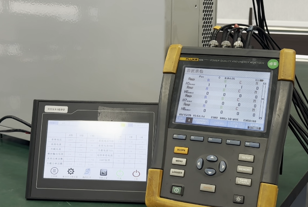
Measure steady-state voltage and current harmonics at the user PCC, not automatically at the nonlinear load or the main switchboard. Before recording, document the one-line diagram, PCC rationale, nominal system voltage, measurement configuration, instrument capability and time synchronization. Determine the short-circuit current at the PCC, ISC, and the maximum demand load current, IL, using methods consistent with the applicable IEEE 519 edition and the project agreement.
Use voltage distortion metrics for the PCC voltage and current demand distortion metrics for the current crossing the PCC. Verify individual harmonic components as well as the aggregate metric. Then compare the correctly aggregated statistics with the limits selected for the applicable edition, voltage class, ISC/IL range and any relevant special system category. Preserve source data, calculations, exclusions and uncertainty so another competent reviewer can reproduce the decision.
IEEE 519 addresses steady-state harmonic goals at the interface between a system owner or operator and a user. The practical question is therefore not “Where is it convenient to connect the analyzer?” but “At which electrical point does responsibility for harmonic performance change?” That point may be at a service entrance, a metering point, a transformer boundary or another location agreed with the utility. The one-line diagram and service arrangement must decide it.
A panel feeding variable-frequency drives can be useful for troubleshooting, filter tuning or source attribution, but it is not necessarily the PCC. Likewise, the low-voltage side of a customer transformer is not automatically interchangeable with a PCC on the medium-voltage side. Transformer connection, impedance, background distortion, phase shift and intervening loads can change what is observed. If a physical connection at the contractual PCC is impractical, document the alternative location and the engineering method used to relate its measurements to the PCC.
Define the assessment boundary before selecting limits. Record the applicable standard edition, project specification, nominal voltage and service topology. Confirm whether the system falls into a special category identified by that edition. For current distortion, establish the correct ISC/IL ratio. Never copy a limit from a previous report merely because the equipment looks similar.
THDv expresses the root-sum-square of voltage harmonic components relative to the fundamental voltage. It describes distortion of the voltage waveform at the observation point. Compliance evaluation also requires attention to individual voltage harmonics, not only the aggregate value.
THDi usually expresses current harmonic content relative to the fundamental current measured during the same interval. It is valuable for diagnosing equipment and comparing waveform distortion under a stated operating condition. However, it can rise sharply at light load because its denominator becomes small, even if the absolute harmonic current has not increased.
TDD, total demand distortion, uses the defined maximum demand load current IL as its denominator rather than the instantaneous fundamental current. This creates a stable demand reference for assessing current distortion at the PCC. TDD and THDi can therefore be numerically different for the same current samples. A report that labels analyzer THDi as TDD without applying the proper IL basis has not demonstrated current compliance.
Start with a current one-line diagram and identify major harmonic sources, capacitor banks, filters and standby generation. Note utility switching and normal configurations. Cover operating states expected to produce high distortion or materially change resonance conditions.
Select a power-quality instrument and sensors suitable for the system voltage, expected current, harmonic range and required aggregation. Verify calibration status and configure ratios, wiring, phase sequence, frequency, recording interval, harmonic groups or subgroups, and clock settings. Perform a connection check before beginning the survey. Record enough pre-test evidence to detect a reversed current transformer, wrong potential-transformer ratio or missing phase.
The monitoring duration must represent the facility’s operating cycle and satisfy the statistical procedure in the applicable standard edition or governing specification. A short spot measurement may support troubleshooting, but it rarely characterizes variable production, weekday/weekend behavior, charging cycles or utility background. Plan time-stamped operating logs so harmonic events can be correlated with load state rather than guessed afterward.
| Plan item | Decision to document | Evidence |
|---|---|---|
| Boundary | Exact PCC and reason | Marked one-line and utility agreement |
| System | Voltage, grounding and normal topology | Nameplates, drawings and switching notes |
| Instrument | Analyzer, probes, ratios and setup | Configuration export and calibration record |
| Coverage | Duration and operating states | Test schedule and production log |
| Reference values | ISC and IL basis | Utility study and demand records |
Capture raw or exportable interval data rather than relying only on screenshots. For each phase, retain fundamental voltage and current, individual harmonic magnitudes, aggregate distortion quantities and demand. Keep timestamps, aggregation settings, instrument flags, gaps and transient or out-of-range indications. Sequence information may be needed where the applicable edition treats certain harmonic groups differently.
The contextual record is equally important. Log transformer and capacitor status, filter mode, generator or converter state, major process steps, production level and unusual switching. Preserve the method and source date for ISC, including the network configuration represented. Preserve the demand history and calculation used to establish IL. If either input is estimated, identify assumptions and sensitivity rather than presenting it as measured fact.
| Record set | Minimum traceability |
|---|---|
| Electrical quantities | Per-phase fundamentals, individual harmonics, aggregate metrics, demand and timestamps |
| Configuration | Wiring mode, sensor ratios, phase labels, aggregation and time settings |
| Reference currents | ISC source and scenario; IL source period and calculation |
| Operations | Load state, switching, filters, capacitors, generation and abnormal events |
| Quality control | Calibration, connection check, data gaps, flags, exclusions and reason codes |
Use the following gate review before signing the result. A “no” should trigger correction, qualification or further measurement—not an unsupported pass.
| Check | Acceptance evidence |
|---|---|
| Applicable requirements identified? | Edition, contract, utility rules and system category are cited |
| PCC confirmed? | Boundary is marked and any proxy location is justified |
| Voltage class confirmed? | Nominal PCC voltage and measurement ratios are documented |
| ISC/IL supported? | Both values, dates, methods and operating assumptions are traceable |
| Representative coverage achieved? | Duration and operating states match the approved plan |
| Data quality accepted? | Calibration, wiring, flags, gaps and exclusions were reviewed |
| Correct metrics calculated? | THDv, TDD and individual harmonics use correct denominators and aggregation |
| Correct limit table selected? | Edition, voltage and ISC/IL basis are stated |
| Statistics verified? | Independent recalculation matches reported values within stated precision |
| Decision reproducible? | Source files, calculations and review trail are retained |
The report should lead with scope and boundary, not a pass/fail badge. Include the marked one-line, PCC description, measurement dates, system configuration, instrument details, applicable requirements and reference-current derivations. Present phase-specific voltage and current results, individual harmonics, aggregate metrics, percentile or time-based statistics required by the applicable edition, and a clear mapping from every result to its selected criterion.
Separate observations from compliance conclusions. Internal bus distortion, equipment heating or filter performance may deserve action without determining PCC compliance. Conversely, an aggregate value below its criterion does not excuse an individual harmonic exceedance. State data gaps, abnormal operations, changed utility topology and measurement uncertainty. Where an exceedance exists, avoid assigning responsibility from amplitude alone; use synchronized measurements, operating correlation or a dedicated harmonic-flow study.
Acceptance should include technical review of formulas and source data. Recalculate a sample of intervals independently, verify denominators, inspect worst-case timestamps and confirm that excluded data were handled consistently. Final sign-off should identify who accepted the PCC, reference values, limit selection and operating envelope represented by the test.
No. It may be, but the PCC is defined by the electrical and contractual boundary. Confirm it from the service arrangement, utility documentation and the applicable requirements. If testing occurs elsewhere, document how the result is translated or justified for the actual PCC.
Not by itself. The display may show THDi referenced to instantaneous fundamental current, while current compliance is assessed using TDD referenced to IL. The test must also address individual harmonics, aggregation, statistical treatment and the correct ISC/IL range.
Long enough to represent relevant operating states and meet the procedure in the applicable standard edition or project specification. There is no responsible universal answer detached from load variability, production schedule and governing requirements. Agree the duration in the measurement plan and explain why the captured period is representative.
Before the next survey, ask the utility and project stakeholders to approve the PCC, applicable requirements, ISC, IL method, monitoring window and operating scenarios. Then issue the field team a controlled setup sheet and require native data exports with the operating log. This modest preparation prevents many disputes that no amount of post-processing can repair.
For a project-specific assessment, engage a qualified power-quality professional to review the one-line, measurement plan and result package against the licensed applicable IEEE 519 edition and local requirements. The goal is not merely a pass label; it is a conclusion that another reviewer can trace from boundary definition to raw data, calculation and acceptance. Applying this IEEE 519 harmonic compliance checklist keeps that review traceable. Related reading: how to read a harmonic spectrum before selecting an AHF and why an AHF is not reducing THDi.


Leave a Comment