An active harmonic filter not reducing THDi is usually a measurement, sensing, or settings problem rather than a device fault. An active harmonic filter (AHF) can be energized, alarm-free, and visibly injecting current while the reported current total harmonic distortion, or THDi, changes very little. That does not immediately prove the filter is defective. The apparent failure may come from comparing unlike measurements, incorrect current-transformer feedback, output-current saturation, an unsuitable control mode, or a network condition outside the filter’s control.
Troubleshoot in sequence: validate measurement, verify the AHF’s electrical inputs and command, then assess the wider power system. Tuning or adding capacity before checking CTs and measurement boundaries can hide the real problem.
If an active harmonic filter is not reducing THDi as expected, first repeat the before-and-after measurements at the same electrical point, load condition, time window, and instrument settings. Then verify CT location, direction, ratio, phase correspondence, and the manufacturer’s open-loop or closed-loop wiring requirement. Confirm that the AHF is not at its RMS or harmonic-current limit, and check which harmonic orders and compensation priorities are enabled.
Do not use THDi as the only acceptance criterion. Because THDi divides harmonic current by the instantaneous fundamental current, it can rise at light load even when harmonic amperes fall. At the point of common coupling (PCC), the relevant assessment may also include individual harmonic currents, total demand distortion (TDD), voltage distortion, true power factor, equipment loading, and the project’s agreed limits. See TDD vs THDi and IEEE 519 at the PCC for the measurement context.
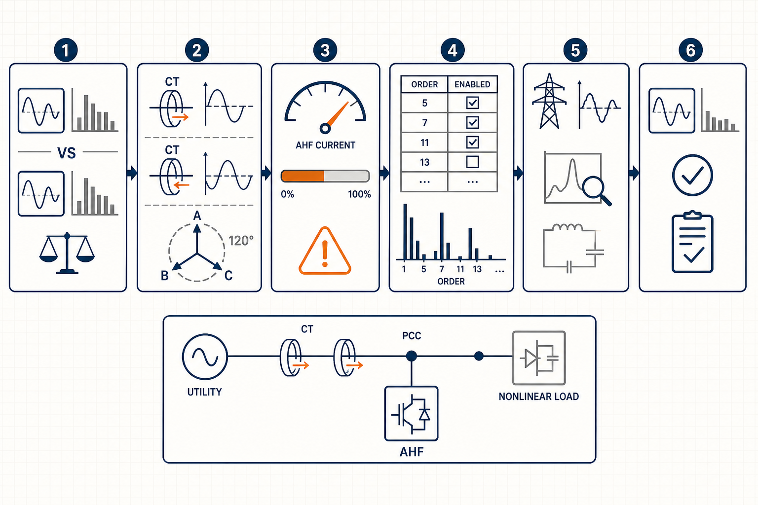
A before-and-after percentage is meaningful only when its numerator, denominator, measurement point, and observation window are comparable. Record fundamental current, harmonic RMS current, individual harmonic spectrum, THDi, voltage THD, and operating load at the same location. A clamp meter at a feeder and an AHF display calculated from source CTs are not necessarily reporting the same boundary.
Align analyzer settings: nominal frequency, current range, CT ratio, aggregation interval, harmonic range, and averaging method. Confirm whether readings are per phase or combined. Variable loads can change state within seconds, so a snapshot cannot be fairly compared with a later ten-minute average.
At low load, reduced harmonic amperes can coincide with an even larger reduction in fundamental current, leaving THDi unchanged or higher. Retain absolute harmonic current and operating state, not just one percentage.
[image: Real power-quality analyzer screenshot showing three-phase current waveforms, harmonic spectrum, fundamental current, harmonic RMS current, THDi, voltage THD, timestamp, and measurement-point label during AHF commissioning.]
The controller calculates compensating current from its sensed current and voltage references. If that feedback is wrong, a perfectly healthy power stage will inject the wrong magnitude or phase. Follow the specific manufacturer’s diagram rather than applying a generic convention.
Start with CT location. Depending on the design, CTs may measure source current in closed-loop compensation or load current in open-loop compensation. They must include the intended nonlinear loads and exclude branches that the control algorithm is not meant to interpret. For placement principles, see where to install an active harmonic filter.
Verify CT direction, secondary polarity, configured ratio, and secure termination. Never open-circuit an energized CT secondary. Trace each chain: the CT on L1 must map to the controller’s L1 current input and L1 voltage reference, likewise for L2 and L3. Do not trust wire colors alone.
A polarity or phase error can reinforce selected harmonics. With the AHF disabled, compare indicated currents, power factor, and phase angles against an independent analyzer. Re-enable it at controlled load and confirm source-side harmonic amperes move in the expected direction. Use software polarity reversal only after identifying and documenting the physical wiring.
An AHF is rated by compensating current, not by the load’s total kVA. Its available RMS current may be shared among harmonic cancellation, reactive-current compensation, and phase balancing. If several functions have equal priority, the unit may have too little remaining capacity for harmonics. Thermal derating, supply-voltage limits, switching-frequency settings, or a module out of service can reduce available output further.
Review commanded and actual current, utilization, limit status, temperature, DC-bus condition, and alarms. Compare harmonic amperes with usable filter current under actual ambient conditions. A unit near its limit may improve the waveform yet miss the target.
Never raise a limit beyond the equipment rating. Confirm load diversity, compensation priorities, cooling, and parallel-module operation. Base any added capacity on measured harmonic current and duty cycle—not THDi alone.
[image: Real AHF commissioning interface showing commanded compensation current, actual output current, utilization or current-limit indicator, enabled functions, DC-bus status, temperature, and active alarms.]
AHFs may offer selective or broadband harmonic compensation, reactive-power correction, and balancing. If a dominant order is disabled, capped, or assigned low gain, distortion may remain high. Triplen harmonics require a suitable topology and neutral connection; do not assume a three-wire AHF can correct four-wire neutral current.
Check enabled orders against a fresh spectrum, plus compensation percentage, priority, response mode, sleep threshold, and sensing selection. Avoid aggressive gain changes: excessive gain can interact with network impedance or amplify noise. For a stable, narrow spectrum, this active-versus-passive filter comparison can frame alternatives, but it does not replace a site impedance review.
| Observation | Check first | Useful evidence | Corrective direction |
|---|---|---|---|
| THDi barely changes, but load varies | Measurement comparability | Fundamental and harmonic amperes with timestamps | Repeat at the same point, load state, and aggregation window |
| One phase worsens after enabling AHF | CT polarity and phase mapping | Phase angles, independent analyzer, wiring trace | Correct CT/voltage correspondence per manufacturer diagram |
| AHF output stays near its maximum | Current capacity and priorities | Utilization, limit flag, temperature, harmonic amperes | Reallocate functions, correct derating issues, or reassess capacity |
| Dominant order remains unchanged | Enabled order and gain | Individual harmonic spectrum and parameter export | Enable/configure the required order within approved settings |
| Display looks good but PCC does not | CT and analyzer locations | Updated single-line diagram and synchronized readings | Align the control boundary with the acceptance boundary |
| A narrow harmonic peak increases | Resonance or voltage distortion | Voltage spectrum, capacitor status, impedance study | Escalate for network study before further tuning |
An AHF controls current at a defined boundary; it cannot guarantee a clean upstream voltage. Voltage harmonics can drive current through capacitors, transformers, cables, and loads. Correlate voltage and current spectra upstream and downstream without inferring causation from one snapshot.
Capacitor banks, reactors, passive filters, transformer reactance, and cable capacitance can create resonance. A sharp increase at one order, unstable filter current, or changes during capacitor switching warrant an impedance study. Do not tune through suspected resonance by trial and error; record the configuration and involve the manufacturer and a qualified power-quality engineer.
Yes. THDi is harmonic RMS current divided by fundamental RMS current. If the fundamental decreases faster than harmonic current, THDi can increase. Compare absolute harmonic amperes, individual orders, load state, and—at the applicable PCC—TDD and the project’s specified limits.
No. A single THDi value is not a complete compliance assessment. IEEE 519 current-distortion evaluation is associated with the PCC and uses defined demand-current and system-strength context, along with individual harmonic limits. Confirm the applicable edition, measurement method, and contractual criteria with the responsible engineer.
Not necessarily. The required rating depends on measured harmonic current, compensation objectives, load diversity, ambient and electrical derating, and whether the same capacity is used for reactive current or balancing. Sizing should use representative spectrum data and manufacturer application guidance.
A useful AHF investigation establishes a trustworthy boundary, proves CT and voltage mapping, shows current headroom, and identifies network interactions. For a project-specific review, prepare the single-line diagram, CT details, AHF model and parameter export, synchronized voltage/current spectra, load states, and acceptance requirements, then discuss them with the supplier or a qualified power-quality engineer.


Leave a Comment