Where should an active harmonic filter be installed? Choose the location from the path of the harmonic current, the loads that need correction and the point where performance will be measured. Installing an AHF at the main switchboard can reduce the harmonic current seen by the transformer or utility, but it does not necessarily remove harmonic current from every internal feeder. A feeder-level or load-side unit may protect local cables and transformers more effectively, although it requires more distributed equipment.
Quick answer: where should an active harmonic filter be installed? Install it at the main bus when the objective is centralized correction for several changing nonlinear loads and compliance is assessed at the incoming point. Install it on a feeder when one process area produces most of the harmonic current or when internal distribution equipment also needs relief. Install it beside an individual load when that load is large, sensitive, isolated or creates a distinctive harmonic spectrum. The final location must be verified with harmonic-current measurements, the single-line diagram, CT placement and all operating configurations.
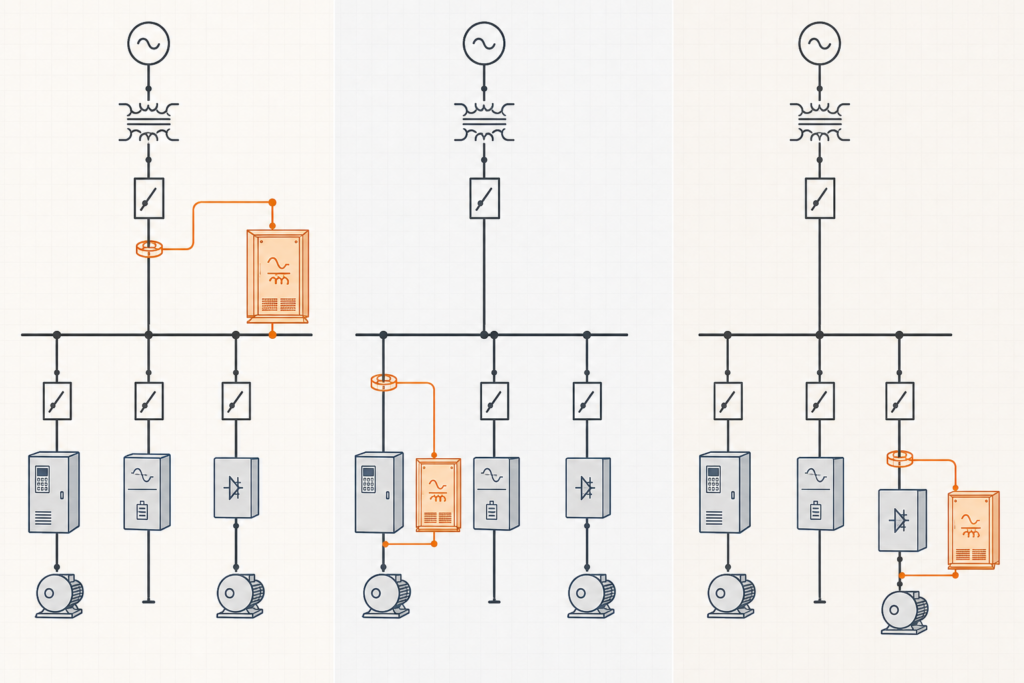
| Installation point | Best fit | Main advantage | Main limitation |
|---|---|---|---|
| Main distribution bus | Many changing nonlinear loads across several feeders | One centralized system can reduce source-side harmonic current | Harmonic current still flows through internal feeders up to the main bus |
| Selected feeder | One production line, UPS group, charger cluster or process area dominates | Relieves the feeder cable and upstream transformer while retaining some centralization | Other harmonic-producing feeders remain untreated |
| Individual load | One large VFD, rectifier, furnace, UPS or dedicated machine | Stops much of the harmonic current close to its source | More units, switchgear space and maintenance points may be required |
| Hybrid arrangement | Large base harmonic sources plus smaller variable loads | Balances local protection, expansion and installed filter current | Requires coordinated controls and CT architecture |
The lowest-cost cabinet location is not automatically the lowest-cost system design. Compare AHF rating, feeder losses, transformer heating, cable utilization, available space, redundancy and future expansion on the same basis.
An active harmonic filter is connected in parallel with the electrical system. Current transformers measure the selected load or source current, the controller extracts the harmonic component, and the converter injects an opposing current. The upstream source should then supply mainly the fundamental current plus any residual distortion outside the filter rating or control target.
The AHF only corrects current that its CTs can see and that lies within the electrical zone defined by the connection point. If a main-incomer AHF measures total source current, it can respond to several downstream feeders. However, the harmonic current from each load still travels through its branch circuit and feeder before reaching the main bus. If a cable, local transformer or generator is overheating, correcting only at the main bus may leave the stressed internal path unchanged.
Use the single-line diagram to mark four items before selecting the location:
A centralized AHF is connected to the main low-voltage bus, normally through a dedicated breaker or fuse arrangement. Its CTs typically measure the incoming current or the combined current of the compensated bus section. This architecture is common when many VFDs, UPS systems, rectifiers, switched-mode supplies or chargers operate with changing diversity.
A centralized unit can share its current capacity across loads that do not peak at the same time. For example, one production line may dominate during the day while a charging or pumping process operates at night. Time-series harmonic amperes can therefore justify a smaller combined rating than the sum of several local units.
A main-bus unit does not prevent harmonic current from flowing between the nonlinear loads and the main bus. That matters when a feeder cable, distribution transformer, generator or local capacitor bank is exposed to the distortion. A single central unit also becomes a common point of capacity and availability: if it reaches current limit or is out of service, all connected loads contribute residual harmonics upstream.
For split-bus switchboards, bus-tie positions must be included in the design. CT zones and filter connections that work with an open tie may become incorrect when the tie is closed. Generator mode can also change source impedance, voltage distortion and the required control settings.
Feeder-level installation places the AHF at the distribution board or motor-control center serving a defined process area. The CTs measure that feeder, and the filter is connected in parallel on the same bus section. This is often the most practical balance between one large centralized unit and many load-side units.
A feeder AHF prevents much of the corrected current from travelling through the feeder’s upstream path. It can also simplify troubleshooting because the measurement zone matches a recognizable process. The design should still check whether harmonic current can circulate through bus ties, capacitor banks or parallel transformers.
Distributed feeder filters can provide operational redundancy. If one unit is unavailable, the remaining areas continue to receive compensation. The trade-off is additional breakers, CTs, cooling, communication and maintenance points.
Load-side installation is appropriate when one large device creates a substantial and identifiable part of the site distortion. Examples can include a high-power six-pulse drive, industrial rectifier, electric furnace auxiliary system, large UPS input or dedicated fast charger.
Placing the AHF close to the load shortens the path of the harmonic current. The branch cable and upstream equipment carry less distortion, subject to the residual target and filter capability. The arrangement also separates that load from changes elsewhere in the plant.
Do not place sensitive power-electronic equipment in a hot, dusty or vibrating location merely to minimize cable length. The AHF still needs acceptable ambient temperature, ventilation, service access, protection and electromagnetic compatibility. If the machine environment is unsuitable, the filter may be installed at the nearest suitable distribution point with the CT and cable arrangement engineered accordingly.
The correct architecture follows the project objective rather than a universal rule.
A hybrid arrangement must not allow several filters to control the same measured current without coordination. Define the CT zones, function priorities and current limits for every operating mode.
Many AHF commissioning problems come from CT architecture rather than converter hardware. The controller must receive the correct phase, direction, ratio and measurement zone.
Source-side CTs measure the residual current after compensation. The controller uses closed-loop feedback to drive source harmonics toward the target. This arrangement can provide accurate source-current control, but the AHF connection and CT locations must be coordinated so the injected current is included correctly in the feedback loop.
Load-side CTs measure the nonlinear load current before the AHF injection point. The controller calculates the required compensating current from the measured load. This can simplify a dedicated-load arrangement, but any unmeasured parallel load is outside the compensation command.
A filter connected to the correct bus with incorrectly placed CTs can under-compensate, oscillate or reinforce the unwanted current.
THDi can rise at light load because its denominator is the fundamental current. A feeder with high THDi may still contribute fewer harmonic amperes than a heavily loaded feeder with a lower percentage. Record individual harmonic amperes, RMS current, THDv, TDD where applicable, load state and measurement location.
At the point of common coupling, evaluate the applicable utility requirement, contract and edition of IEEE 519 rather than applying one internal equipment reading to the entire facility. The TDD vs THDi guide explains why the denominator and measurement point change the conclusion. For equipment selection, use the harmonic spectrum and residual target together with the AHF sizing guide.
Once the electrical zone is selected, verify that the physical installation supports continuous current and maintenance.
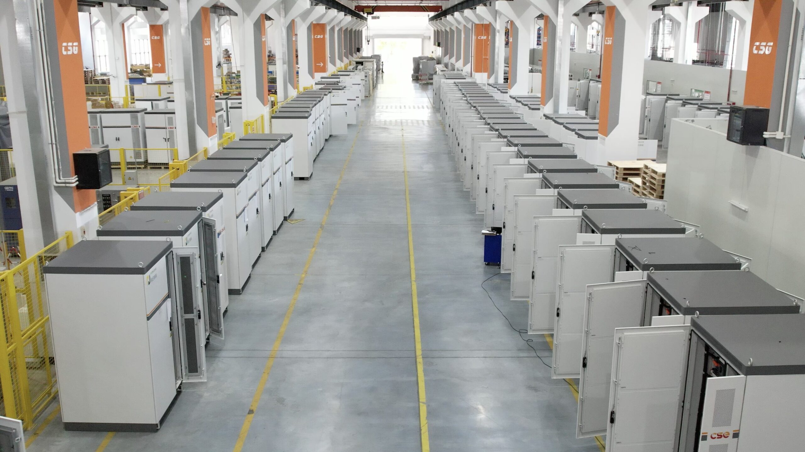
A practical installation must provide orderly cabinet access, ventilation clearance and maintainable cable routes. Factory layout reviews should confirm that doors, fans, modules and terminations remain accessible after adjacent equipment is installed.
The AHF location should also support commissioning measurements. Provide safe test points for current, voltage and communication so residual performance can be demonstrated under representative operating conditions.
Consider a 400 V plant supplied by a 2,000 kVA transformer. Three feeders serve a VFD production line, a UPS-supported process and a group of smaller rectifier loads. Measurements show the following peak harmonic current:
| Feeder | Peak harmonic current | Operating pattern | Internal concern |
|---|---|---|---|
| VFD production line | 150 A | High during two production shifts | Long feeder and cable heating |
| UPS process | 75 A | Continuous | Sensitive process and generator operation |
| Small rectifier group | 55 A | Intermittent | No local thermal constraint |
A single main-bus AHF could reduce incoming harmonic current, but the 150 A from the VFD line would continue to flow through its long feeder. A feeder-level AHF for the production line therefore addresses both the source target and the local cable concern. The remaining UPS and rectifier currents can be reviewed for one main-bus unit, separate feeder correction or source improvements.
If the UPS must operate during generator mode while the main switchboard arrangement changes, a dedicated feeder filter may provide a clearer measurement and control zone. The final ratings should come from time-series harmonic amperes, simultaneous peaks, supported harmonic orders, derating and the required residual current—not from adding the three percentages shown by separate meters.
Yes, if it is connected and measured at a common bus that includes those feeders. Its current rating, CT zone and control stability must cover the combined operating cases. It will reduce upstream current but will not remove harmonics from the internal feeder sections between each load and the common bus.
Close placement reduces the path of harmonic current and can relieve the branch circuit, but it is not always the best overall design. Environment, switchgear access, load diversity, maintenance and the required measurement point may favor feeder-level or centralized installation.
They can be installed at an incoming measurement point when the architecture and controller support it. Confirm CT ratio, polarity, cabling distance, bus configuration and whether the injected filter current is correctly represented in the control loop. Never select the CT position without the supplier’s approved diagram.
The strongest AHF design identifies where harmonic current originates, which equipment must be relieved and where residual performance will be accepted. A main-bus unit offers centralized capacity, a feeder unit protects a defined process area, and a load-side unit stops current closest to a dominant source. A hybrid system may provide the best technical and lifecycle result when these objectives overlap. So where should an active harmonic filter be installed? In the zone where harmonic current originates, where equipment must be relieved and where residual performance will be accepted.
Review the active versus passive harmonic filter guide before selecting the mitigation technology. Then prepare the single-line diagram, transformer data, load schedule, harmonic spectra, CT locations, operating modes and residual target using the AHF, SVG and capacitor-bank quote checklist. For an installation review, send the project data to Elumotive.


Leave a Comment