The choice between three-wire vs four-wire active harmonic filters hinges on neutral current and load type. Many active harmonic filter (AHF) projects begin with a current rating, yet the first design decision should be more basic: is the compensation point three-wire or four-wire? A 3P3W feeder and a 3P4W distribution board can show similar phase-current distortion while requiring different AHF hardware, sensing, protection, and conductor arrangements.
Choosing correctly is not simply a matter of counting conductors at the transformer. Engineers must identify where the AHF will connect, whether line-to-neutral loads exist downstream, which harmonic sequences dominate, and whether neutral-current reduction is part of the performance objective. This article provides a practical framework for making that choice.
Use a 3P3W AHF when the compensation bus has three phase conductors, no distributed neutral, and loads are predominantly three-phase equipment such as variable-frequency drives, rectifiers, UPS inputs, or industrial power converters.
Consider a 3P4W AHF when the target bus distributes a neutral to substantial single-phase nonlinear loads, especially IT equipment, LED lighting, office electronics, point-of-sale systems, or mixed commercial loads. A suitable four-wire AHF can compensate phase harmonics and imbalance and can inject neutral current to reduce source-side neutral current, subject to its topology, controls, rating, and installation configuration.
The final selection must be based on measured phase and neutral waveforms at the proposed point of connection—not on the building label alone.
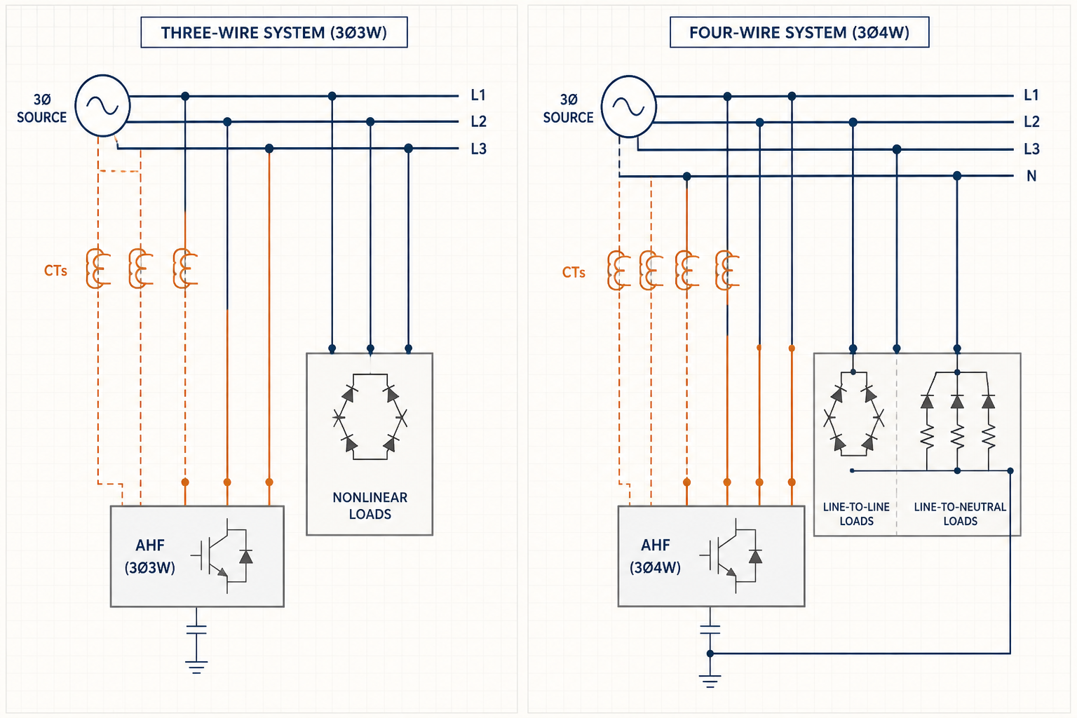
An AHF is connected in parallel with the electrical system. It measures current, calculates the unwanted harmonic and—where supported—reactive or unbalanced components, then injects compensating current. The supply therefore carries a cleaner residual current while the load continues drawing its characteristic waveform.
In a 3P3W system, the AHF has no neutral connection. Its phase-current references are constrained by Kirchhoff’s current law: instantaneous phase currents sum to zero at the connection point. There is no independent path for zero-sequence current. This arrangement is well suited to three-phase loads and phase-to-phase systems.
A 3P4W AHF adds a neutral current path and control capability. Many products use a four-leg inverter; others use alternative DC-link arrangements. These topologies are not interchangeable merely because a terminal is marked “N.” Confirm whether the selected unit actively compensates neutral current, its continuous neutral-current rating, and how total output capacity is allocated among phase harmonic, reactive, imbalance, and neutral compensation.
[image: Inside a low-voltage AHF cabinet during a four-wire installation, showing clearly identified L1, L2, L3, and neutral conductors, CT secondary wiring, protective device, cable routing, bonding, and warning labels; no brand logos.]
A 3P3W AHF is normally the appropriate choice at a bus serving three-phase, three-wire nonlinear equipment. Typical applications include motor-control centers with six-pulse drives, process rectifiers, welding systems, three-phase UPS rectifier inputs, and industrial converters supplied without a neutral.
It may also be correct on the primary side of a delta-wye transformer even when the secondary serves line-to-neutral loads. However, that does not mean it can solve secondary neutral heating. Zero-sequence triplen currents do not pass through the transformer to the upstream three-wire system in the same form. If the problem exists on the four-wire secondary, compensation generally needs to be evaluated on that secondary bus.
Three-wire selection can reduce conductor and switchgear complexity, but it should never be used simply to save cost where the performance specification includes neutral-current mitigation.
A 3P4W AHF should be evaluated wherever a neutral is distributed and nonlinear single-phase loads form a meaningful share of demand. Common examples are data rooms, hospitals, schools, retail facilities, office floors, airports, hotels, and mixed-use buildings.
The strongest indicators are high neutral RMS current, prominent third-harmonic current, unequal phase loading, transformer or neutral heating, and nuisance operation of protection associated with distorted current. Measure under representative operating states: occupancy, lighting schedules, server utilization, charging cycles, and switched load combinations can materially change the result.
A four-wire AHF is not automatically the cure for every neutral issue. First exclude loose connections, incorrect neutral bonding, wiring errors, phase allocation problems, and undersized conductors. Also verify that the AHF’s neutral compensation objective applies on the source side of its connection; load-side branch neutral currents still physically flow between loads and the compensation node.
Triplen harmonics are odd multiples of the third harmonic: 3rd, 9th, 15th, and so on. In a balanced positive-sequence fundamental system, phase currents are displaced by 120 degrees. Third-harmonic components from similar line-to-neutral loads are approximately in phase, so they add in the neutral instead of canceling.
For an ideal balanced case dominated by third harmonic, the neutral third-harmonic component can approach three times the per-phase third-harmonic current. Real installations also contain unequal fundamentals, different harmonic spectra, phase-angle diversity, and load variation, so neutral RMS current must be calculated from measured vector components rather than a simple arithmetic rule.
A 3P3W AHF can compensate positive- and negative-sequence harmonic currents available in its three-wire path, but it cannot inject an independent neutral current. A properly designed 3P4W AHF can create the zero-sequence compensation path needed to reduce upstream triplen current. Performance still depends on bandwidth, control priority, available ampere capacity, CT placement, conductor impedance, and resonance conditions.
| Selection factor | 3P3W AHF | 3P4W AHF |
|---|---|---|
| Connection | L1, L2, L3 | L1, L2, L3, N |
| Typical loads | Three-phase drives, rectifiers, industrial converters | Mixed loads and substantial single-phase nonlinear loads |
| Zero-sequence path | No independent path | Supported when designed for active neutral compensation |
| Neutral-current reduction | Not available directly | Possible upstream of the compensation point |
| Imbalance compensation | Phase compensation within three-wire constraints | Can address phase imbalance and neutral return, product-dependent |
| Key sizing data | Phase harmonic spectrum and operating diversity | Phase spectra, neutral spectrum, imbalance, and simultaneous priorities |
| Installation checks | Phase CT position, polarity, sequence, and protection | All three-wire checks plus neutral routing, rating, and bonding arrangement |
A 400/230 V office distribution board supplies LED lighting, workstation power supplies, and several small UPS systems. A survey at weekday peak records phase RMS currents of 180 A, 165 A, and 175 A. Each phase contains approximately 38–44 A of third-harmonic current, while the neutral measures 118 A RMS. The third harmonic dominates its spectrum. The project objective is to reduce source phase distortion and neutral loading at this board.
Because the loads are line-to-neutral, the bus is 3P4W, and neutral mitigation is explicit, a 3P4W AHF is the correct architecture to evaluate. A 3P3W unit could inject phase harmonic current but could not provide the independent zero-sequence current path required for the neutral objective.
The engineer should not select a rating by assuming that 3 × 44 A equals the required AHF size. Harmonic components have phase angles, the neutral includes several orders and imbalance, and the AHF may share capacity across four conductors. Exported waveform data should be applied to the vendor’s sizing method, with margin for operating variation. Commissioning should then verify source-side phase spectra, source-side neutral RMS current, thermal conditions, and operation across representative load states.
Physically possible does not mean functionally sufficient. It may compensate selected phase-current components, but it cannot independently inject neutral current. Use it only when a documented study shows that neutral and zero-sequence compensation are not required and the manufacturer approves the connection.
No. The neutral must be sized and protected according to applicable codes, expected nonlinear loading, fault conditions, and engineering calculations. The AHF is mitigation equipment, not a substitute for safe conductor design, correct bonding, or maintenance.
No single device guarantees compliance. IEEE 519 assessment is made at the defined point of common coupling and depends on system impedance, load current, background voltage distortion, demand, and operating conditions. Establish the compliance target, model or measure the system, select the AHF, and verify results after commissioning.
The three-wire versus four-wire decision becomes straightforward when the compensation boundary and current paths are clear. Elumotive can review single-line diagrams, load schedules, harmonic logs, neutral-current data, and performance objectives to help develop an application-specific AHF selection and commissioning plan. Provide representative measurements and the proposed connection point to begin a technical review.


Leave a Comment