Transformer overheating with nonlinear loads deserves a measured answer. A transformer feeding variable-frequency drives, UPS systems, switch-mode power supplies, LED drivers or EV chargers may run hotter than its kVA loading suggests. The tempting conclusion is “harmonics.” Sometimes that is correct—but overload, high ambient temperature, obstructed airflow, failed fans, loose joints, phase imbalance, overexcitation and insulation deterioration can produce similar symptoms.
With transformer overheating with nonlinear loads, the useful question is not whether harmonics exist. It is whether the measured harmonic spectrum creates unacceptable transformer and neutral heating under the actual duty cycle, and which intervention removes the constraint without solving the wrong problems.
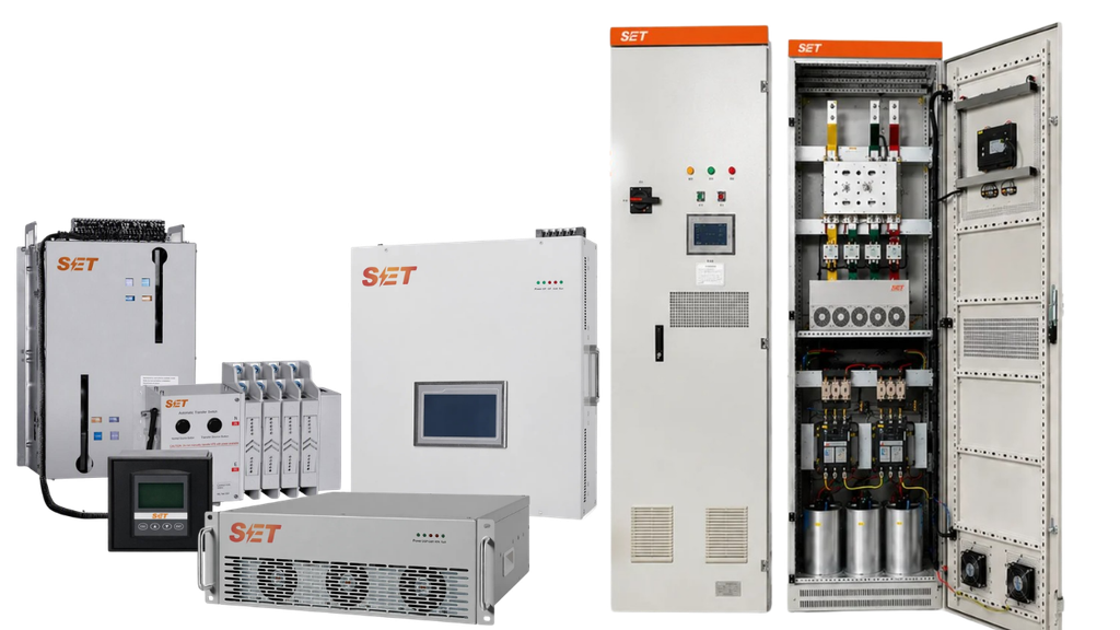
Do not choose a K-rated transformer, derating percentage or active harmonic filter (AHF) from THDi alone. First establish loading, ambient and cooling conditions; inspect connections; record phase and neutral RMS current; capture the current spectrum by harmonic order; measure voltage distortion; and trend temperature at comparable load.
If an existing transformer is healthy but harmonic loss makes its permissible load lower than demand, apply a manufacturer- or IEEE-based derating assessment. If capacity, age or condition already justifies replacement, specify a transformer designed for the measured nonlinear-load duty. If the transformer is adequately sized and sound but the facility needs lower upstream harmonic current across changing loads, an AHF may be the better system-level measure. Often the answer is a combination: correct defects first, then reassess filtering or replacement.
A linear load draws current broadly proportional to sinusoidal voltage. A nonlinear load draws pulses or switched current containing integer multiples of the fundamental frequency. Transformer heating then changes through several mechanisms:
Nameplate kVA and conventional power factor therefore do not describe the complete thermal duty. Nor does one THDi number: two spectra with the same THDi can have different high-order content and heating impact.
Hotspots at winding regions, terminals or neutral connections need different interpretations. A single hot lug points first toward contact resistance or conductor termination. Broad, repeatable transformer heating that tracks nonlinear loading supports a loss-related diagnosis, but must still be compared with the manufacturer’s temperature limits and stated ambient assumptions.
In a three-phase, four-wire wye system, triplen harmonics—3rd, 9th, 15th and so on—are zero-sequence components. Instead of cancelling in the neutral like balanced fundamental currents, they can add arithmetically. A neutral may therefore carry substantial current even when phase currents look balanced. Check the neutral conductor, bus, terminal and source path; do not infer neutral loading from phase imbalance alone.
Useful signatures include high crest factor, dominant 5th and 7th components from six-pulse conversion, and voltage notching. They are clues, not universal fingerprints.
Follow site safety procedures. Use suitably rated instruments and qualified personnel.
K-factor is a spectrum-weighted index in which harmonic current components are weighted by the square of harmonic order. It describes harmonic heating severity of a load spectrum; a transformer’s K-rating describes a design capability under specified conditions. A higher K-rating is not an efficiency grade, does not cancel harmonics and does not cure overload, poor ventilation or bad joints.
Derating keeps an existing transformer below the load that would exceed its thermal capability with the measured spectrum. It can be appropriate when equipment condition is good, the load profile is stable and reduced capacity is operationally acceptable. The allowable load should come from applicable guidance and transformer-specific data—not a generic THDi-to-derating chart.
Replacement is favored when required capacity exceeds defensible derated capability, insulation condition is poor, expansion is planned, losses or reliability justify renewal, or the original transformer is unsuitable for sustained nonlinear duty. Specify the actual spectrum, RMS load, ambient, enclosure and neutral requirements rather than selecting K-13 or K-20 by habit.
Active filtering injects controlled current to counter selected load harmonics. It suits variable loads, multiple nonlinear feeders on a common bus, or a need to reduce upstream distortion without replacing a sound transformer. Check filter current rating, four-wire/neutral capability, target spectrum, CT location and polarity, system impedance, generator modes, capacitor banks and future load. An AHF cannot repair thermal damage or a resistive connection.
| Option | Best fit | Main advantage | Key limitation or check |
|---|---|---|---|
| Correct defects | Loose joints, blocked cooling, imbalance or control failure | Removes the root cause | Requires safe inspection and verification |
| Derate existing transformer | Sound unit, stable spectrum, spare capacity | Low equipment change | Reduces usable capacity; needs defensible loss data |
| K-rated or harmonic-duty replacement | Capacity or condition already supports replacement | Thermal design matched to nonlinear duty | Does not reduce harmonic current elsewhere |
| Active harmonic filter | Variable multi-load bus needing upstream mitigation | Adaptive compensation at the point of connection | Needs correct sensing, rating and system study |
| Load segregation or passive measures | Predictable loads or practical feeder redesign | Can isolate or reduce the source | Passive resonance and operating-range checks are essential |
First: Is the temperature actually outside the transformer manufacturer’s permitted conditions? If not, continue trending rather than declaring failure.
Second: Is heating localized at a joint, associated with ventilation, or explained by fundamental-frequency overload or imbalance? Correct that condition before buying harmonic equipment.
Third: Do logged spectra and loading show harmonic loss is material? If no, investigate ambient, overexcitation, cooling and condition. If yes, calculate permissible loading using transformer-specific information.
Fourth: Can operations remain below that limit with margin? If yes, document derating, alarms and periodic verification. If no, compare replacement, load redistribution and filtering.
Finally: Is the objective transformer capacity only, or bus-wide harmonic performance? Replacement improves transformer tolerance; an AHF reduces selected current harmonics upstream. Where both objectives apply, evaluate lifecycle cost and resilience together.
Assume a balanced load has harmonic current components, expressed in amperes, of 100 at the fundamental, 30 at the 3rd, 20 at the 5th and 10 at the 7th. Ignoring other components, total RMS phase current is:
I_RMS = √(100² + 30² + 20² + 10²) = 106.8 A
A normalized K-factor for this illustrative spectrum is:
K = [1²(100²) + 3²(30²) + 5²(20²) + 7²(10²)] / 106.8² = 2.89
For balanced, in-phase 3rd-harmonic phase currents in a four-wire wye system, that component can produce 3 × 30 = 90 A in the neutral, while the balanced fundamental cancels. Real spectra include phase angle, more orders and operating variation. The calculated 2.89 is not by itself a transformer selection or derating instruction; the transformer’s eddy-loss characteristics, loading standard and manufacturer data are still required.
No. Measure the spectrum and phase currents. Triplen harmonics are a common cause in four-wire systems, but imbalance, wiring conditions and measurement errors must also be considered.
No. It is constructed to tolerate specified harmonic heating. It generally does not cancel the nonlinear load’s harmonic current, so upstream power-quality objectives require separate evaluation.
Potentially it can reduce harmonic loss at the monitored point, but the post-filter spectrum, residual RMS load, ambient, transformer condition and manufacturer limits must be reassessed. Do not assume the nameplate rating is automatically restored.
Before requesting a quotation for transformer overheating with nonlinear loads, assemble a one-line diagram, transformer nameplate and test data, 7-day load and harmonic trends where operations vary, phase and neutral spectra, thermal records, ambient conditions, future load forecast and the exact performance objective. A qualified power-quality engineer and the transformer or filter manufacturer can then compare derating, replacement and filtering on the same evidence—without promising an unsupported temperature drop or energy saving. Related reading: where to install an active harmonic filter and how to read a harmonic spectrum before selecting an AHF.


Leave a Comment