A power quality audit checklist keeps an AHF, SVG, or hybrid selection decision grounded in measured data rather than assumptions. Power quality equipment should be selected from measured system behavior, not a single current reading or utility bill. An active harmonic filter (AHF), static var generator (SVG), and hybrid arrangement address different duties; similar symptoms may have different causes. Low power factor or overheating can involve reactive power, harmonics, imbalance, resonance, or neutral loading.
A structured audit identifies the point of common coupling (PCC), operating modes, dominant loads, harmonic spectrum, reactive demand, voltage conditions, and installation constraints. If essential data are missing, a supplier can prepare only a budgetary estimate—not a final design, guaranteed rating, or final installation plan.
Before selecting an AHF, SVG, or hybrid solution, define the compliance and operational objective; collect single-line diagrams, transformer and conductor data, existing capacitor information, and load schedules; then conduct synchronized measurements through representative production cycles. Record voltage, current, kW, kvar, power factor, THDv, current spectrum, TDD where applicable, imbalance, neutral current, events, and demand peaks. Correlate every measurement with equipment status.
Use an AHF when harmonic current is the primary problem, an SVG when fast-changing reactive power or imbalance dominates, and a coordinated hybrid when both require dynamic correction. Do not finalize topology or rating until site data, measurement location, operating scenarios, ambient conditions, and expansion plans have been verified.
Write the problem statement before connecting an analyzer. “Improve power quality” is too broad. A useful objective identifies the affected bus, observed symptom, performance target, and verification point. Examples include meeting a specified harmonic limit at the PCC, preventing transformer or neutral overheating, stabilizing power factor during rapidly changing loads, reducing voltage fluctuation, or releasing capacity constrained by reactive or harmonic current.
Also distinguish compliance from equipment protection. IEEE 519 evaluation generally focuses on the PCC and uses TDD rather than a load-side THDi snapshot; see the explanation of TDD versus THDi and the IEEE 519 PCC. An internal bus may need a stricter operational target even when PCC values are acceptable.
Obtain the latest single-line diagram and verify it in the field. Record utility supply characteristics, transformer kVA, impedance, vector group, secondary voltage, parallel operating arrangements, generator modes, bus-tie status, feeder protection, cable or busbar ratings, neutral configuration, grounding method, and short-circuit information if available.
Document existing detuned or conventional capacitor banks, passive filters, reactors, UPS systems, drives, and renewable or storage converters. Capacitors can change resonance conditions, so their step sizes, reactor tuning, controller logic, and switching sequence matter. Note panel ingress protection, ambient temperature, altitude, ventilation, access, cable route, available space, and communications requirements. Installation location affects both performance and economics; compare the options in this guide to active harmonic filter installation location.
List major loads by feeder and operating state. For each load, record quantity, rated and typical current, kW, power factor, converter type, pulse number where known, duty cycle, simultaneity, switching frequency if relevant, and future expansion. Flag variable-frequency drives, rectifiers, welders, furnaces, cranes, elevators, data-center supplies, LED lighting, battery chargers, and single-phase electronic loads.
The inventory must describe combinations, not just nameplate totals. Identify normal, peak, partial-load, maintenance, generator, bus-tie, and capacitor-switching states. Note whether loads are steady, cyclic, or regenerative. This mapping prevents sizing around an unrepresentative snapshot.
[image: A qualified power quality engineer wearing appropriate PPE connecting a Class A power quality analyzer to a low-voltage switchboard during an onsite audit, with insulated probes, current clamps, barriers, and panel labels clearly visible]
Use a suitable calibrated power quality analyzer and have installation performed by authorized personnel under the site’s electrical safety procedure. Confirm current-transformer orientation, phase association, voltage reference, clamp range, sampling settings, clock synchronization, and instrument wiring before logging. Incorrect phase mapping can produce believable but unusable power and power-factor data.
Measure first at the defined PCC or main bus, then at candidate compensation buses and major nonlinear feeders as needed. Logging should cover complete representative cycles—often several working days, and longer where weekly schedules or intermittent processes matter. Capture minimum, maximum, average, and time-trended values for RMS voltage and current, frequency, kW, kvar, kVA, true and displacement power factor, voltage and current imbalance, THDv, THDi, individual harmonic magnitudes and phase angles, neutral current, demand, and relevant events.
For harmonic compliance, collect the demand information needed to determine TDD and the applicable current-distortion limit. Record voltage notching, transients, flicker, dips, or swells when symptoms suggest them. Photograph or log operating states so peaks can be tied to actual machines, capacitor steps, or switching events rather than treated as unexplained anomalies.
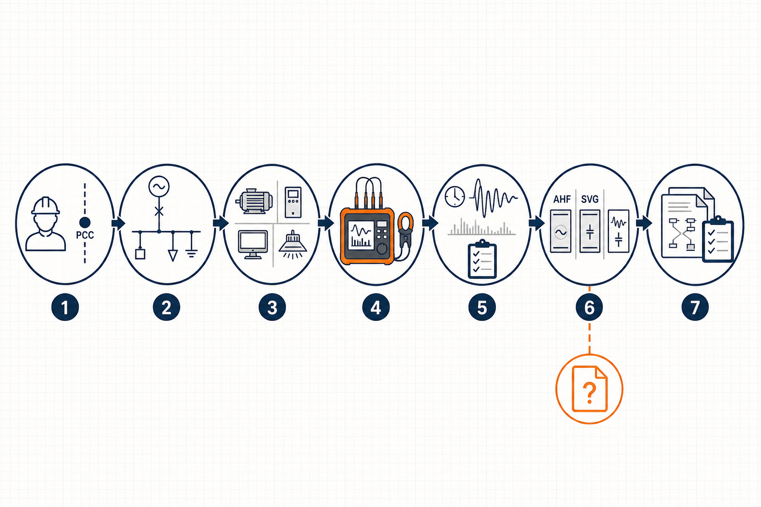
Use the checklist below to control data quality before requesting a firm proposal.
| Category | Required data | Why it matters | Check |
|---|---|---|---|
| Objective | Target bus, PCC, symptom, limit, operating scenarios | Defines success and verification point | □ |
| Source | Utility, transformer, generator, impedance, fault level | Affects harmonic limits and system interaction | □ |
| Distribution | Verified single-line, bus ties, feeders, conductor and neutral ratings | Supports topology and installation choice | □ |
| Loads | Nonlinear loads, duty cycles, simultaneity, regenerative modes, expansion | Explains spectrum and future demand | □ |
| Existing correction | Capacitor steps, reactors, passive filters, switching logic | Identifies resonance and coordination risks | □ |
| Measurements | Time trends, kW, kvar, PF, THDv, THDi, spectrum, TDD inputs, imbalance, neutral current | Establishes actual correction duty | □ |
| Events | Dips, swells, flicker, transients, notching, process timestamps | Separates filterable issues from other disturbances | □ |
| Environment | Voltage, frequency, temperature, altitude, enclosure, ventilation, space | Supports equipment derating and layout | □ |
| Commercial basis | Tariff, penalties, downtime cost, growth plan, acceptance criteria | Enables lifecycle comparison and scope clarity | □ |
Check analyzer exports as well as summary screenshots. Raw interval data, waveform or event records, harmonic tables, instrument configuration, and measurement-point photographs allow engineers to validate conclusions. If one operating mode was not captured, state the gap explicitly and plan a follow-up measurement.
An AHF injects compensating current to reduce selected harmonic currents and can often provide some reactive or imbalance compensation within its available current capacity. It is usually the leading family when nonlinear loads drive excessive harmonic current across changing operating states. Selection still requires the harmonic spectrum, required residual level, bus voltage, load diversity, CT arrangement, and candidate connection point.
An SVG dynamically supplies or absorbs reactive current and can respond much faster than mechanically switched capacitor steps. It suits rapidly varying inductive or capacitive demand, unstable power factor, and certain imbalance requirements. Its operating principle and control role are summarized in how a static var generator works. An SVG should not be assumed to solve a harmonic compliance problem unless the proposed product and design explicitly provide that function.
A hybrid solution may combine AHF and SVG functions, active equipment with detuned capacitors, or centralized and feeder-level units. It can be economical when base reactive demand is predictable but harmonic and dynamic kvar duties vary. Coordination is essential: capacitor switching changes the network, while allocating too much AHF capacity to kvar correction may leave insufficient current for harmonics during peak production.
Other findings may require correcting connections, conductors, grounding, capacitor tuning, or transformer issues before active compensation. An audit should select a remedy, not justify a predetermined product.
This matrix supports shortlisting only. Final rating and configuration depend on verified measurements and engineering review.
| Observed dominant condition | Preliminary family | Evidence required | Key caution |
|---|---|---|---|
| Variable harmonic current exceeds target | AHF | Spectrum, time trend, TDD basis, load states | Check voltage distortion and resonance |
| Fast-changing kvar or poor displacement PF | SVG | kvar profile, PF trend, step response need | Do not equate low true PF with kvar alone |
| Harmonics plus dynamic reactive demand | AHF + SVG or multifunction hybrid | Simultaneous harmonic and kvar peaks | Allocate current capacity by worst credible mode |
| Stable base kvar plus variable distortion | Detuned capacitors + AHF | Base-load profile, impedance and resonance review | Coordinate tuning and switching |
| Localized nonlinear feeder problem | Feeder-level AHF | Upstream and feeder measurements | Confirm CT and connection location |
| Insufficient or nonrepresentative data | Measurement campaign first | Missing scenarios and validated raw data | Budget estimate only; no final design |
Compare alternatives against harmonic targets, dynamic kvar duty, losses, modularity, maintainability, footprint, environmental rating, protection coordination, and expansion. A lowest-kVA comparison can mislead when products have different simultaneous-function limits.
A decision-ready audit package should contain:
The commercial request should align with this package. The AHF, SVG and capacitor-bank quote checklist can help standardize the information sent to vendors. Final documents should clearly separate measured facts, calculations, assumptions, and guarantees.
It should cover every representative operating mode, not an arbitrary duration. A continuous week is often useful for facilities with weekday, weekend, shift, and production-cycle variation. A shorter campaign may work for a stable, repeatable process; intermittent furnaces, welders, cranes, seasonal HVAC, generator tests, or batch operations may require longer or targeted logging. Verify that the highest relevant load combinations were actually captured.
They can support a rough budget but not final selection. Bills do not provide harmonic spectrum, phase relationships, short-duration kvar peaks, imbalance, neutral current, candidate-bus conditions, or operating-mode correlation. Transformer rating is not the required compensation current. Without validated measurements and system data, any rating remains assumption-based and must be labeled budgetary.
Usually both serve different purposes. The PCC is essential for utility-interface assessment and standards-based evaluation. Measurements at major nonlinear feeders reveal which loads contribute distortion and whether local compensation can prevent harmonic current from circulating through upstream conductors. Main-bus and candidate installation-point data support centralized options. Use synchronized instruments or aligned timestamps when comparing locations.
A good audit reduces uncertainty before equipment is purchased. Share the verified single-line diagram, load inventory, raw analyzer files, operating-state log, site constraints, and target limits with the engineering team. Elumotive can review the package, identify remaining data gaps, and develop a budgetary concept or—when the evidence is complete—a final technical proposal with defined assumptions and verification criteria.
Start with the quote and data checklist to organize your submission. If critical measurements are still missing, schedule the next audit step rather than converting assumptions into a final design.


Leave a Comment