Whether an active harmonic filter with capacitor bank protection can coexist depends on detuning and control coordination. Installing an active harmonic filter (AHF) on a bus that already has a power-factor correction capacitor bank is technically possible—and often useful. The AHF can inject currents that oppose selected harmonic currents, while the bank supplies fundamental-frequency reactive power. They are not inherently incompatible.
The qualification matters: a capacitor changes network impedance, and an AHF is a closed-loop converter. Engineers should evaluate resonance, switching states, current-transformer (CT) location, control priorities, loading, and the harmonic spectrum before combining them.
Yes, an active harmonic filter can work with a capacitor bank, provided resonance and control interaction are assessed. A common arrangement lets the capacitor bank handle bulk kvar economically and the AHF mitigate non-linear-load harmonics dynamically. If the AHF also provides reactive compensation, one controller must have a defined role so that it does not repeatedly counteract the automatic power-factor controller.
An AHF should not be treated as a substitute for checking capacitor voltage, reactor tuning, step contactors, ventilation, fuse condition, or the available short-circuit level. If an existing bank overheats or loses fuses, begin with a structured investigation such as this guide to capacitor bank overheating and fuse failure.
A shunt AHF measures load or source current, extracts selected unwanted components, and injects a compensating current at the point of connection. Depending on its design and settings, it may address harmonic current, current unbalance, and some reactive current. Its usable correction is limited by converter current rating, thermal conditions, response settings, and the spectrum it is commanded to compensate.
A capacitor bank supplies leading reactive power at the fundamental frequency. Automatic banks switch steps to follow changing demand; fixed banks remain connected. In harmonic-rich systems, series reactors may be added to form a detuned bank. Detuning shifts the bank’s resonant behavior away from dominant characteristic harmonics and limits harmonic current entering the capacitors, but it does not make the installation immune to every frequency or operating state.
Passive filters are different again: their reactor-capacitor branches are intentionally tuned or damped to present low impedance over a frequency range. For selection context, see active versus passive harmonic filters.
[image: Technician inspecting a detuned low-voltage capacitor bank, including reactor condition, step contactors, fuses, ventilation paths, and nameplates]
Every supply has inductance from transformers, cables, generators, and upstream equipment. A connected capacitor bank forms an LC network with that inductance. Near the network’s parallel-resonant frequency, impedance can rise sharply. Harmonic current already produced by drives, rectifiers, UPS equipment, LED power supplies, or other converters can then create greater voltage distortion. In a series-resonant path, current through the capacitor branch can rise.
The risk is operating-state dependent. Switching one capacitor step changes capacitance; transferring to a generator changes source impedance; connecting another transformer changes fault level; and adding drives changes harmonic current. Therefore, a study based only on the maximum kvar state can miss a problematic partial-step combination.
An AHF may reduce source-side harmonic current, but it cannot guarantee that no resonant point exists. Control bandwidth, output impedance, current limit, and connection location also matter. The objective is stable operation across credible source, load, and capacitor-step states.
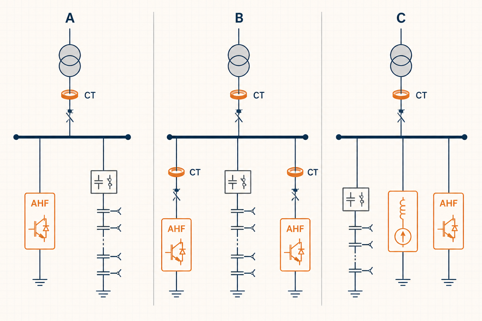
Both devices connect to the main low-voltage bus. The bank supplies bulk kvar in steps; the AHF is primarily assigned harmonic current. Incomer CTs allow the AHF to regulate the source current seen upstream. This architecture is straightforward, but the review must include every material bank-step combination and alternate source mode.
A central detuned bank corrects the facility’s fundamental reactive demand, while smaller AHFs are installed close to major non-linear-load groups. Local compensation can keep harmonic current out of upstream cables and transformers. It also limits the area affected by one filter reaching its current limit. The trade-off is more equipment, more CT sets, and more coordination settings.
The capacitor bank covers steady base kvar. A properly designed AHF with reactive-current capability—or a separate static var generator (SVG)—trims rapid reactive changes, while harmonic filtering remains an explicit function. Deadbands, response times, limits, and priorities must be coordinated. Otherwise, the fast converter may chase each bank step, and the bank controller may respond to the converter, causing unnecessary switching.
| Architecture | Best fit | Main advantage | Critical review point |
|---|---|---|---|
| Central AHF + detuned bank | Concentrated loads on one main bus | Simple central monitoring and maintenance | Resonance across all bank steps and source states |
| Central bank + feeder AHFs | Several separated nonlinear load groups | Harmonic current is controlled near its source | CT boundaries, diversity, and cumulative ratings |
| Staged bank + dynamic kvar trim | Fast-changing reactive demand | Economical base kvar with rapid fine control | Controller ownership, deadbands, and step hunting |
CT placement defines what the AHF tries to correct. With closed-loop source-current control, CTs are normally placed at the incomer so they measure the combined effect of loads, the bank, and the AHF at the intended point of correction. They must be on the correct side of the AHF connection, with verified phase association, polarity, ratio, and summation direction. A reversed CT can command reinforcement rather than cancellation.
Feeder-level AHFs require local CTs that measure only the intended load group. Avoid overlapping control zones unless the manufacturer has validated a master-slave or coordinated multi-unit scheme. Two independent filters reacting to the same current without coordination can divide current unpredictably or interact dynamically.
Decide which device owns fundamental kvar control. If the bank is primary, the AHF can prioritize harmonics and use only spare current capacity for kvar trim. Configure compatible power-factor targets, delays, and deadbands. The bank controller’s sensing point should represent the desired utility-side power factor, and its response should be slow enough not to chase transient AHF action.
Consider a facility with variable-speed drives, an existing automatic capacitor bank, and reports of reactor heat during high production. Measurements show that load mix and active bank steps change throughout the day. This information alone does not justify selecting an AHF ampere rating or declaring resonance.
A defensible decision process is:
The likely architecture may be a detuned staged bank with a central AHF, but that remains an engineering selection, not a guaranteed outcome. The final choice depends on the impedance scan, spectra, switching states, and equipment data.
No. It can reduce selected harmonic current within its rating and control range, but it does not remove resonance under every topology or correct an underrated, damaged, or poorly ventilated bank. Capacitor and reactor suitability still require verification.
There is no universal answer based only on physical order along the bus. The connection point and CT boundary must match the intended control zone. Engineers should evaluate the one-line diagram, cable impedance, bank switching states, and manufacturer control requirements together.
They can, but their roles must be separated. A practical strategy is to let the bank provide economical base kvar and allow the AHF to trim fast variations only when current capacity is available. Coordinated targets, delays, deadbands, and priorities prevent hunting.
For an engineering review, assemble the one-line diagram, source data, harmonic logs, capacitor and reactor nameplates, step sequence, CT details, load schedule, and environmental conditions. Elumotive News’ linked checklists can help organize those inputs for discussion with the AHF, bank, and system-study providers. The goal is a traceable design decision—not a generic promise that one device will fix every power-quality symptom.


Leave a Comment