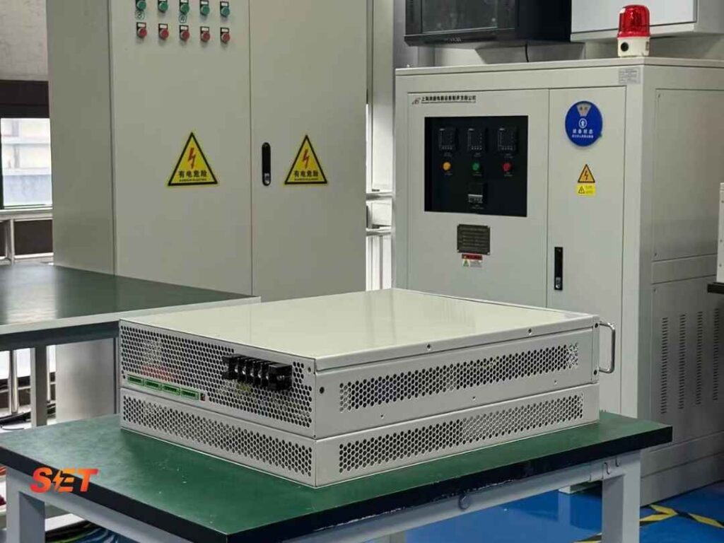
BESS reactive power support is technically possible because a battery energy storage system uses a bidirectional power converter that can control active and reactive current. The battery supplies the active-energy component, while the inverter can generate or absorb reactive power within its current and voltage limits. The difficult question is not whether BESS can provide kvar, but how much is available at each operating point and whether that capacity remains dependable when the battery is delivering its primary MW service.
Quick answer: a BESS can often provide voltage control and power-factor correction, especially when active-power dispatch is below the inverter rating. A dedicated STATCOM is still justified when full reactive capacity must remain available regardless of state of charge or MW output, when overload and fault-response requirements exceed the BESS converter capability, or when project risk and availability require an independent device.
The starting point is the inverter apparent-power limit:
S² = P² + Q²
S is apparent power in MVA, P is active power in MW and Q is reactive power in Mvar. A 10 MVA inverter delivering 8 MW has an ideal circular-limit reactive capability of √(10² − 8²) = 6 Mvar. At 10 MW, the same idealized calculation leaves no continuous Mvar headroom. At zero MW, up to 10 Mvar appears possible. Real equipment has additional limits from DC voltage, semiconductor current, modulation, transformer voltage, temperature and control priorities, so the manufacturer’s P-Q capability chart must replace the simplified circle in final design.
| BESS operating state | Reactive-power opportunity | Main constraint |
|---|---|---|
| Idle, grid connected | Potentially high kvar headroom | Auxiliary losses, DC-link and contractual mode |
| Partial MW charge/discharge | Shared P-Q capability | Inverter MVA and thermal limit |
| Rated MW output | May be small or unavailable | Current limit and active-power priority |
| Low/high state of charge | Reactive power may still be possible | Control policy, DC voltage and availability |
| Low-voltage fault | Dynamic reactive current may be prioritized | Current ceiling and grid-code sequence priority |
Reactive power does not consume battery energy in the same way as sustained MW discharge, but state of charge still affects availability. If the battery is unavailable because of protection, maintenance or a DC-side limit, the converter may also be unavailable. Some systems support a STATCOM mode with the battery isolated; others require the DC system online. Reactive current also produces conduction and transformer losses, so continuous overnight voltage support changes auxiliary consumption and thermal loading even when net MW is close to zero.
Ask the supplier to identify the conditions under which “zero-MW Mvar” is guaranteed: minimum and maximum state of charge, battery contactor status, DC-link source, ambient temperature, grid voltage, cooling redundancy and duration. The answer should appear in the availability model and performance guarantee, not only in a capability brochure.
This approach can improve asset utilization. For example, a solar-plus-storage plant may use the BESS inverter for nighttime voltage control when active-power dispatch is low. During the day, the plant controller can share the reactive target across PV inverters, the BESS and any dedicated compensation. The dispatch should minimize losses and respect each device’s current and temperature limits rather than forcing one asset to carry all kvar.
A dedicated STATCOM separates voltage-support capacity from the BESS active-power schedule. This is valuable when the network operator requires the full Mvar range at maximum MW export or import. It also allows the STATCOM rating and overload envelope to be optimized for faults and fast voltage recovery, while the BESS inverter is optimized for energy throughput and battery life.
A STATCOM is not automatically better. It adds capital cost, losses, switchgear, transformer capacity, footprint and maintenance. The decision should compare lifecycle value: reduced renewable curtailment, avoided grid penalties, higher BESS MW availability, improved fault ride-through and redundancy against the extra equipment cost.
Step 1: define the service at the point of connection. State steady-state Mvar range, target voltage or power factor, voltage droop, response time, fault-current priority and required availability. Avoid a single requirement such as “±20 Mvar” without voltage and duration.
Step 2: build simultaneous P-Q cases. Include maximum discharge, maximum charge, zero-MW operation, low and high grid voltage, hot ambient temperature, one converter block unavailable and future expansion. Overlay the required points on the supplier’s capability curve.
Step 3: model dynamics and current limiting. Use RMS studies for plant-level regulation and electromagnetic-transient studies where weak grids, grid-forming control or fault interactions matter. Confirm how the controller transitions between active-current and reactive-current priority.
Step 4: compare architectures. Options include an oversized BESS PCS, a dedicated STATCOM, or a smaller STATCOM working with reserved BESS headroom. Include transformer and cable MVA, losses, auxiliary consumption, outage risk and model-maintenance obligations.
Assume a 50 MW BESS uses 55 MVA of converter capacity and the grid study requires ±25 Mvar at the point of connection. At 50 MW, the ideal circle provides √(55² − 50²) ≈ 22.9 Mvar, already below the requirement before transformer and voltage limits are applied. At 40 MW, ideal headroom rises to about 37.7 Mvar. The owner therefore has three credible choices: limit active power when maximum reactive support is demanded, increase PCS MVA, or add a dedicated STATCOM.
If grid conditions require 25 Mvar only during rare low-voltage events, temporary active-power curtailment and reactive-current priority may be economical. If ±25 Mvar must be continuously available while 50 MW is dispatched, a dedicated or hybrid solution is easier to guarantee. The final result also depends on the voltage at the inverter terminals: reactive capability usually changes across the grid-voltage range.
Storage connection queues are growing faster than many networks can absorb. In September 2026, Ofgem reported around 90 GW of battery projects in Great Britain’s transmission connection queue compared with substantially lower projected need. At the same time, the IEA’s Electricity 2026 analysis emphasizes the need for system flexibility. Projects that define measurable grid services and credible availability will be easier to study than those that list broad capabilities without operating constraints.
Possibly, if the converter can energize its DC link and operate in STATCOM mode with the battery unavailable. This is design-specific and must be confirmed by the supplier. Auxiliary power and thermal limits still apply.
Reactive current does not create the same cell energy throughput as MW cycling, but it increases inverter, cable and transformer losses and can raise temperature. That may affect PCS component life and cooling duty, so it belongs in the lifecycle model.
They can if voltage, winding arrangement, protection, harmonics and simultaneous MVA loading are engineered accordingly. A shared transformer can reduce cost but creates a common outage point and may constrain the combined P-Q envelope.
Elumotive supplies medium-voltage dynamic compensation for renewable and storage projects. Review the 3–35 kV SVG/STATCOM platform and our guide to SVG applications in solar PV and battery systems. To compare a BESS-only, STATCOM or hybrid design, send the P-Q cases and grid-study requirements.

