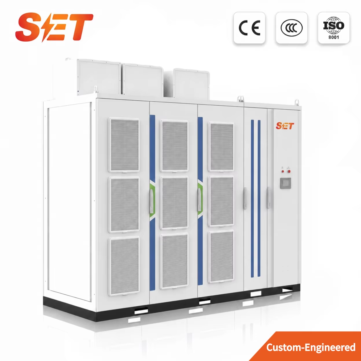
Model: SET-MV-SVG / STATCOM
SET 3–35kV medium-voltage SVG / STATCOM with project capacity up to ±150 Mvar, cascaded H-bridge IGBT topology, ≤5 ms controller response and indoor/outdoor configurations.
SET MEDIUM-VOLTAGE POWER QUALITY SOLUTION
Modular cascaded H-bridge reactive-power compensation for transmission grids, substations, heavy industry, rail traction and arc-furnace loads.
SET MV SVG uses cascaded multi-stage H-bridge power cells with fully controlled IGBT devices. The converter is connected to the grid through a reactor or step-up transformer. By adjusting the amplitude and phase of the converter-side voltage—or directly controlling AC current—the system absorbs or supplies reactive current dynamically.
When converter voltage equals grid voltage, the SVG does not exchange reactive power.
The SVG operates as a continuously adjustable reactor to absorb reactive power.
The SVG operates as a continuously adjustable capacitor to supply reactive power.
Improves power factor, compensates inductive or capacitive reactive-power demand and reduces line losses.
Rapidly changes reactive current to suppress voltage fluctuation and flicker caused by abrupt load changes.
Supports line voltage, increases transmission capability, damps oscillations and improves stability during disturbances.
Compensates negative-sequence current caused by load or network impedance imbalance.
| Rated output voltage | 3kV, 6kV, 10kV, 20kV, 22kV, 24kV, 33kV, 35kV… |
|---|---|
| Rated capacity | −150 Mvar to +150 Mvar |
| Main circuit | Three-phase |
| Control supply | DC 220V / AC 380V |
| Allowable power fluctuation | ≤120% |
| Output harmonic compliance | IEEE Std 519-1992; GB/T 14549-93 |
| Control modes | Fixed reactive power, fixed voltage, fixed power factor, comprehensive voltage / power-factor control |
| Control platform | DSP + FPGA |
| Grid frequency | 50 / 60 Hz |
| Controller response | ≤5 ms |
| Carrier control | Phase-shifting to reduce output harmonics |
| Auxiliary functions | Fault recording, harmonic-current compensation, negative-sequence-current compensation |
| Run / stop | Touch screen, DCS or upper-level communication |
| Communication | RS485, Ethernet, optical fiber, RS232, 4G |
| Local / remote operation | Touch screen and cabinet controls; remote SCADA / AVC |
| Protection level | Indoor IP23; outdoor IP56 |
| Operating temperature | −10°C to +40°C |
| Storage / transport | −40°C to +85°C |
| Humidity / altitude | ≤95% RH, non-condensing; ≤2000 m standard |
Comprehensive protection includes overcurrent, quick-break, overload, instantaneous voltage drop, cooling-fan failure, power-unit failure, PT disconnection, unit overvoltage, abnormal system voltage and input-voltage imbalance. Online self-checking and modular redundancy support continuous operation and easier maintenance.
For medium-voltage harmonic control, the brochure specifies total harmonic-current compensation ≥70%, single-order compensation ≥80%, selectable filtering from the 2nd to 25th order, and harmonic-compensation response ≤10 ms.
Send the grid voltage, required reactive-power range, short-circuit capacity, single-line diagram and installation conditions. SET engineers will prepare the topology, cooling and enclosure proposal.