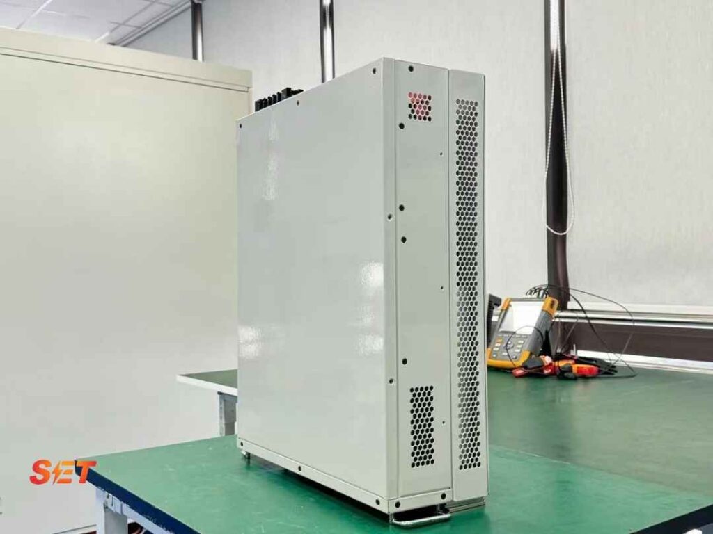
AI data center power quality is becoming a design constraint rather than a commissioning afterthought. High-density GPU clusters, UPS rectifiers, cooling drives and rapidly changing compute loads can create harmonic current, voltage variation and reactive-power demand at the same time. A facility may have enough installed megawatts yet still experience nuisance trips, transformer heating or unstable bus voltage because the electrical system was sized for steady demand instead of fast, converter-dominated operation.
Quick answer: protect an AI data center by monitoring from the PCC down to the UPS and cooling distribution, separating harmonic and reactive-current problems, and assigning each mitigation device a defined task. Active harmonic filters (AHFs) reduce selected harmonic currents, static var generators (SVGs) regulate dynamic reactive power and imbalance, while UPS controls, transformers, conductors and protection settings must be coordinated with both.
Conventional data-center design often assumes that diversity across thousands of IT loads will smooth the aggregate demand. AI training clusters challenge that assumption. Large groups of accelerators can enter and leave high-compute states together, causing megawatt-scale ramps at the facility bus. The electrical effect depends on the server power supplies, UPS topology, energy-storage controls, transformer impedance and upstream grid strength. The same power step that is invisible on a strong utility network can produce a measurable voltage deviation on a weak or heavily loaded connection.
The IEA’s 2026 Energy and AI analysis reports rapid growth in data-center electricity use and highlights the unusually fast power fluctuations associated with AI workloads. The operational lesson is practical: annual energy consumption and peak demand are not enough. Designers also need ramp rate, repetition, duration and the minimum short-circuit strength expected at the connection point.
| Mechanism | Typical source | What to measure | Primary response |
|---|---|---|---|
| Current harmonics | UPS, server PSUs, cooling VFDs | Individual orders, THDi, TDD, neutral current | AHF, converter settings, phase/load distribution |
| Dynamic reactive power | Transformers, motors, changing load | kvar, displacement PF, voltage trend | SVG or coordinated inverter control |
| Rapid active-power ramps | Synchronized GPU workload | MW/s, event duration, bus voltage | UPS/BESS control, grid-strength review |
| Voltage events | Utility faults, transfer operations, inrush | Sag depth, duration, phase angle, interruptions | UPS ride-through, protection coordination |
These mechanisms interact, but they should not be collapsed into one “power factor” number. True power factor includes distortion; displacement power factor describes the phase relationship of the fundamental voltage and current. An AHF can improve true power factor by reducing harmonic current, but it does not supply sustained active power during a rapid load step. An SVG can inject or absorb reactive current quickly, yet it cannot correct an upstream interruption. Clear definitions prevent equipment from being purchased for a problem it cannot solve.
Use synchronized instruments where possible. A voltage dip at the main bus and a simultaneous increase in UPS input current tell a different story from a utility-originated sag that appears first at the PCC. Trend RMS values, unbalance and harmonic spectra together with workload or BMS timestamps. A one-line screenshot at nominal load can miss the exact transition that causes a trip.
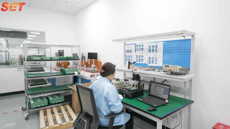
Modern power supplies with power-factor-correction stages can have lower current distortion than older six-pulse inputs, but thousands of units operating together still create a meaningful harmonic spectrum. UPS rectifiers, VFDs and auxiliary loads add their own signatures. A high THDi reading at light load may reflect a small fundamental current rather than an extreme harmonic current, so the PCC assessment should include TDD and the agreed demand-current reference. Our TDD vs THDi guide explains the calculation and its IEEE 519 context.
Also inspect individual orders and the neutral. Triplen harmonics can accumulate in four-wire systems, while characteristic orders from six-pulse drives may dominate the cooling plant. Transformer derating, cable ampacity and neutral sizing depend on actual RMS current and loss distribution. An AHF rating should be based on the harmonic amperes that must be cancelled under coincident loading, with thermal and future-expansion margin. The process is described in our AHF sizing guide.
Reactive-power demand can change when cooling equipment stages, transformers energize or UPS operating modes change. Fixed capacitor steps may be too slow or too coarse, and capacitor banks can interact with the system impedance at harmonic frequencies. An SVG measures current and voltage, calculates the required fundamental reactive component and injects compensating current through a voltage-source converter. This makes it suitable for rapidly varying kvar demand and systems where both leading and lagging correction are required.
SVG capacity should not be selected from the monthly utility power-factor value alone. Build a kvar-versus-time envelope, identify the fastest credible step, specify the target power factor or bus-voltage range, and confirm overload duration. If harmonic compensation is also required, decide whether separate AHF and SVG devices, an advanced SVG, or a coordinated hybrid system offers the required performance and redundancy. See our data-center SVG and AHF integration guide.
A resilient design uses layers. First, specify low-distortion UPS and IT power supplies and coordinate their controls. Second, distribute single-phase loads to control imbalance and neutral current. Third, place AHFs close enough to major nonlinear groups to keep harmonic current out of shared transformers and feeders. Fourth, install SVG capacity at the bus where dynamic kvar correction produces the required voltage or power-factor result. Finally, validate the combined system during mode transfers, generator operation, maintenance bypass and partial-load conditions.
Consider a 10 MW hall supplied through two redundant transformer paths. Measurements show 420 A of combined harmonic current on the active path during a representative high-compute period, with peaks during cooling transitions. Reactive demand varies from 150 kvar leading to 900 kvar lagging, and the operator plans a 30% IT expansion. The engineering solution should not simply specify a 420 A AHF and a 900 kvar SVG. It should first allocate harmonic current by bus, confirm N and N+1 operating modes, define the residual TDD target, apply diversity to the expansion case and calculate the worst kvar step when one path is unavailable.
A modular arrangement might split compensation across the two electrical paths so that maintenance does not remove all mitigation. The final ratings depend on measured spectra, voltage, altitude, ambient temperature, enclosure ventilation, overload requirement and CT architecture. This design process produces testable acceptance criteria: residual harmonic amperes and TDD at named points, power factor over a stated load range, response to a defined kvar step and stable operation during transfer tests.
An AHF can correct harmonic and, depending on its design, some reactive or unbalance current. It does not supply the active energy required by a megawatt load ramp. UPS, BESS, generator and utility-interface controls must address active-power balance.
Central compensation can protect the PCC efficiently, while hall-level equipment prevents harmonic or reactive current from using shared internal capacity. Large facilities often need both layers. Measurement results and redundancy objectives should determine the split.
Send the single-line diagram, voltage and frequency, transformer ratings and impedance, UPS topology, generator data, load and kvar trends, harmonic spectrum by order, neutral current, target limits, ambient conditions, redundancy philosophy and expansion forecast. For an engineering review, contact Elumotive with the measurement files rather than screenshots alone.

