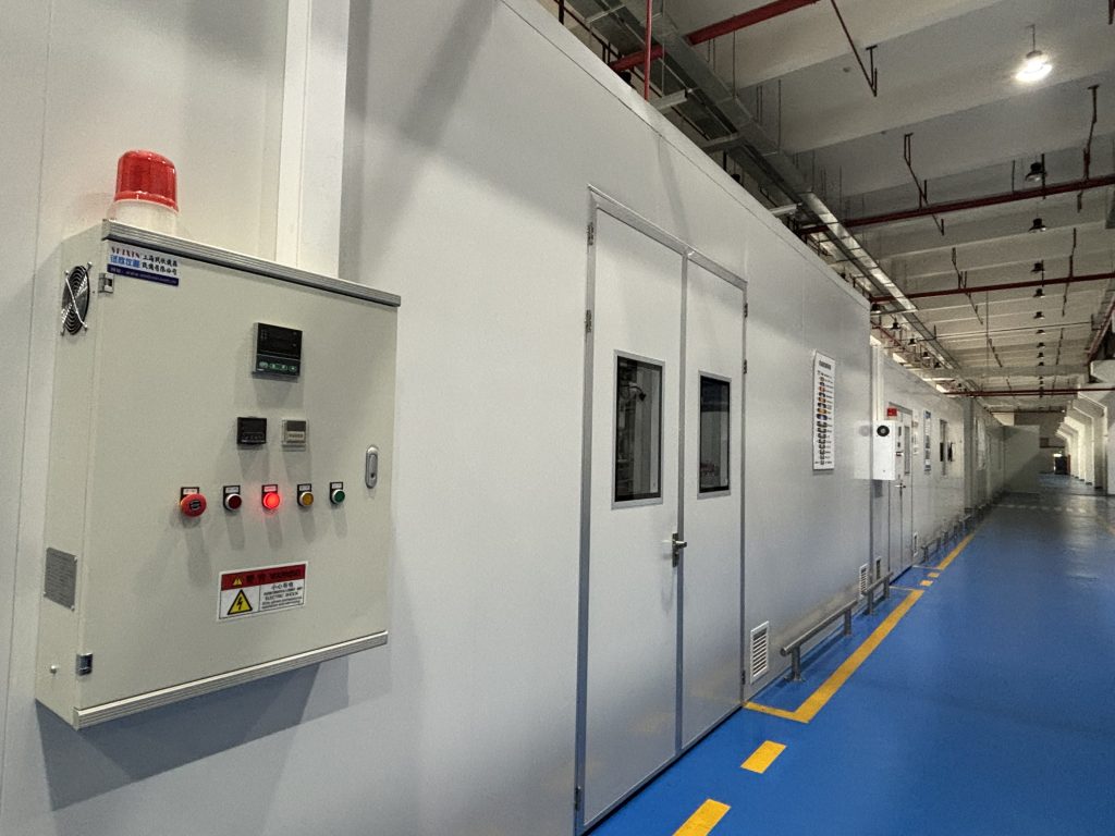
This solar PV SVG case study shows how a 200 kVAr Static Var Generator helped an industrial rooftop-PV site improve high-side power factor from 0.77 to 0.94. The first SVG installation corrected reactive power while production was running. Six months later, the factory stopped production and the electrical system shifted into a PV-dominant operating mode. Grid active-power consumption fell sharply, but the transformer still required magnetizing reactive power. Elumotive therefore reviewed measurements at the high-voltage side and optimized the SVG control strategy so compensation followed the utility-side target rather than only the low-voltage load.
Confidentiality note: The customer name, exact location, meter number, billing records, commercial amounts, and dates have been withheld. The technical sequence, 200 kVAr SVG rating, and measured power-factor result are retained from the project record.
| Item | Anonymized project detail |
|---|---|
| Application | Industrial rooftop solar PV site in China |
| Main issue | Low utility-side power factor and recurring reactive-energy charges |
| Installed equipment | One 200 kVAr low-voltage Static Var Generator (SVG) |
| Original operating mode | Factory production running with rooftop PV generation |
| Changed operating mode | Production stopped; PV generation remained online |
| Root cause after the change | Grid active-power demand dropped, while transformer magnetizing reactive power remained |
| Engineering action | Measure at the high-voltage side and optimize SVG control logic/compensation target |
| Recorded result | High-side power factor increased from 0.77 to 0.94 |
Power factor is the ratio between active power and apparent power. At an industrial site, motors, transformers, cables, and other inductive equipment require reactive power even when the utility supplies less active energy because a rooftop PV system is operating.
Consider a simplified condition in which the plant load still needs active power and reactive power, but the PV inverter supplies part of the active power locally. The utility meter then sees less imported kW while kvar demand may remain. Because the denominator used to evaluate power factor changes, the measured power factor at the point of common coupling can fall.
The effect becomes more pronounced when production stops. The site may export active power from the PV system, yet the transformer continues to draw magnetizing current. A controller that measures only a low-voltage feeder may not see the complete reactive-power requirement at the utility measurement point.
For a practical overview of the available correction methods, see How to Improve Power Factor in Industrial Plants.
The project initially operated as a normal industrial facility with rooftop solar generation. Measurements showed that the existing compensation arrangement was not maintaining the required power factor across the real load cycle. A 200 kVAr Static Var Generator was installed on the low-voltage side.
An SVG is a power-electronic reactive-power compensator. It samples system current and injects a controlled current that offsets the reactive component within the device rating. Unlike a contactor-switched capacitor bank, it does not depend on fixed capacitor steps. This makes it suitable for sites where reactive demand changes quickly or where both leading and lagging conditions may occur.
After commissioning, the site's measured power factor improved and the reactive-energy charge issue was initially resolved. The system continued to operate normally for approximately six months.
The electrical operating condition changed materially: production stopped while the solar PV system remained in service. The site was no longer a factory load partly supported by PV; it became a PV-dominant system with very low grid active-power consumption and periods of export.
The reactive-power charge then returned. This did not automatically mean that the 200 kVAr SVG had failed or that its rating was too small. It meant that the original control boundary no longer represented the condition seen by the utility meter.
Three factors mattered:
This distinction is especially important for EPCs and plant owners designing PV-connected industrial systems. Equipment should be selected and controlled for every intended operating mode: full production, light load, night operation, high PV generation, and export.
Shanghai Elumotive Technology reviewed the case as a system-level power-quality problem rather than treating the utility charge as proof that more equipment was required.
The engineering sequence was:
This approach avoided a common mistake: increasing compensation capacity before confirming whether capacity, sensing, control logic, or measurement location was the actual constraint.
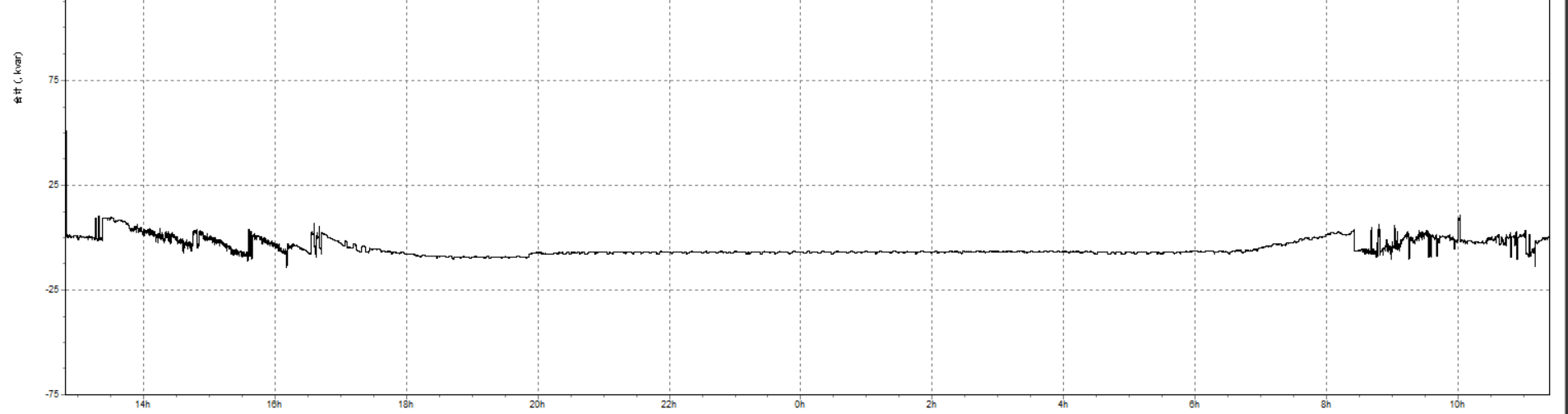
Figure 1. An anonymized reactive-power trend recorded after the SVG control strategy was optimized. Customer identifiers and billing information are not included.
| Evaluation point | Before optimization | After optimization |
|---|---|---|
| High-side power factor | 0.77 | 0.94 |
| Production status | Stopped | Stopped |
| Solar PV status | Operating | Operating |
| Transformer reactive demand | Not fully included in the original target | Included in the coordinated compensation target |
| SVG hardware | 200 kVAr unit installed | Same 200 kVAr unit, with optimized control strategy |
| Main engineering change | Low-voltage-focused compensation | High-side-informed compensation control |
The result demonstrates why a solar PV SVG case study should report more than the device rating. The one-line diagram, CT location, control target, transformer behavior, utility metering point, and operating schedule all influence the final outcome.
A Static Var Generator was appropriate because the site needed adjustable compensation across changing operating modes. In a conventional capacitor bank, compensation is divided into fixed steps. A step can be too small, too large, or too slow when the site's kvar demand changes rapidly or crosses between lagging and leading conditions.
An SVG can regulate reactive current continuously within its rating. That flexibility helps with PV-connected systems where active-power flow can change quickly with irradiance and production load. However, an SVG is not a substitute for a correct electrical study. The device still requires proper current-transformer polarity, sensing location, control settings, cable and protection design, thermal conditions, and commissioning measurements.
For selection trade-offs, read Static Var Generator vs Capacitor Bank. If the site also has high current harmonics, compare the functions of an Active Harmonic Filter and Static Var Generator.
Confirm where the utility calculates power factor and reactive energy. A low-voltage reading may not include transformer losses or other upstream components that are visible at the billing meter.
Record data during maximum production, minimum production, high PV generation, low irradiance, import, and export. A solution tuned for one mode may not meet the target in another.
The controller can only compensate what it measures. CT placement, phase order, polarity, ratio, and communication or remote-setpoint logic must match the single-line design.
Use trend data and allow appropriate engineering margin. The required capacity depends on the reactive-power envelope and control objective, not simply the transformer's nameplate rating.
PV inverters and industrial nonlinear loads can affect the harmonic environment. If capacitor banks are present, evaluate resonance and RMS loading. The article Why Capacitor Banks Fail in Harmonic Systems explains the main risks.
Commissioning should include trend records at the relevant measurement point. Periodic review is also necessary when production schedules, transformer configuration, PV capacity, or tariff rules change.
Solar PV usually reduces the active power imported from the grid. Reactive demand from transformers, motors, and cables may not fall at the same rate. The utility therefore sees fewer imported kW relative to kvar, which can lower the measured power factor.
It can, provided the system is engineered so the SVG receives a representative measurement or control target and has enough current capacity. Transformer reactive demand, CT placement, communication, protection, and the utility measurement point must all be considered.
Measurements indicated that the changed compensation boundary and control target were the key issues. Optimizing the strategy allowed the installed 200 kVAr unit to address the high-side requirement. Adding capacity before diagnosing the control point could have increased cost without solving the root cause.
It can be suitable where reactive demand is stable, harmonic conditions are acceptable, and switching steps can maintain the required target without overcompensation. Rapidly changing or bidirectional reactive demand often favors an SVG or a coordinated hybrid system.
An SVG is primarily selected for dynamic reactive-power compensation. Some advanced products can provide limited harmonic or imbalance functions, but their current capacity is shared. Where harmonic current is the main problem, an Active Harmonic Filter should be evaluated separately or as part of a coordinated solution.
Provide the single-line diagram, utility voltage, transformer rating and impedance, CT locations, PV inverter capacity, import/export modes, 24-hour kW/kvar/power-factor trends, harmonic measurements, existing compensation equipment, target power factor, and installation photos.
This anonymized solar PV SVG case study shows that a recurring low-power-factor problem is not always a capacity problem. When production stopped and PV generation continued, the transformer and utility-side measurement boundary became decisive. High-side diagnosis and a revised control strategy enabled the installed 200 kVAr SVG to raise the recorded power factor from 0.77 to 0.94.
Shanghai Elumotive Technology supplies Static Var Generator (SVG/STATCOM), Active Harmonic Filter (AHF/APF), and coordinated power-quality solutions for renewable-energy and industrial projects. Contact Elumotive with your single-line diagram and measurement data for a project-specific review.