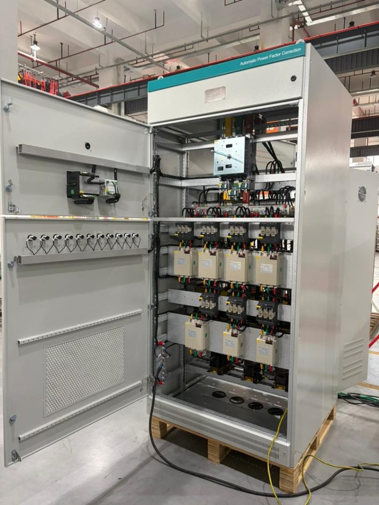
Capacitor banks fail in harmonic-rich power systems because their impedance decreases as frequency rises. They can therefore absorb harmonic current far above their intended fundamental-frequency duty. If the capacitor bank and upstream system inductance form a resonant circuit near a dominant harmonic, current and voltage may be amplified further. The result can be overheating, bulging cans, blown fuses, contactor damage, nuisance trips, or repeated early replacement. The safe response is not simply to install a heavier capacitor: measure the harmonic spectrum, check resonance risk, and select a detuned bank, Active Harmonic Filter, Static Var Generator, or combined solution for the actual load profile.
Power-factor capacitors are designed mainly to supply reactive power at the fundamental frequency—50 or 60 Hz. Their capacitive reactance is:
Xc = 1 / (2πfC)
As frequency increases, reactance falls. A capacitor therefore presents much lower impedance to the 5th, 7th, 11th, and higher-order harmonic currents produced by variable-frequency drives, UPS systems, rectifiers, welders, EV chargers, and switched-mode power supplies.
This does not mean every nonlinear load will immediately damage a bank. The outcome depends on the harmonic spectrum, system short-circuit strength, transformer impedance, installed capacitance, switching steps, loading pattern, and the location of the measurement point.
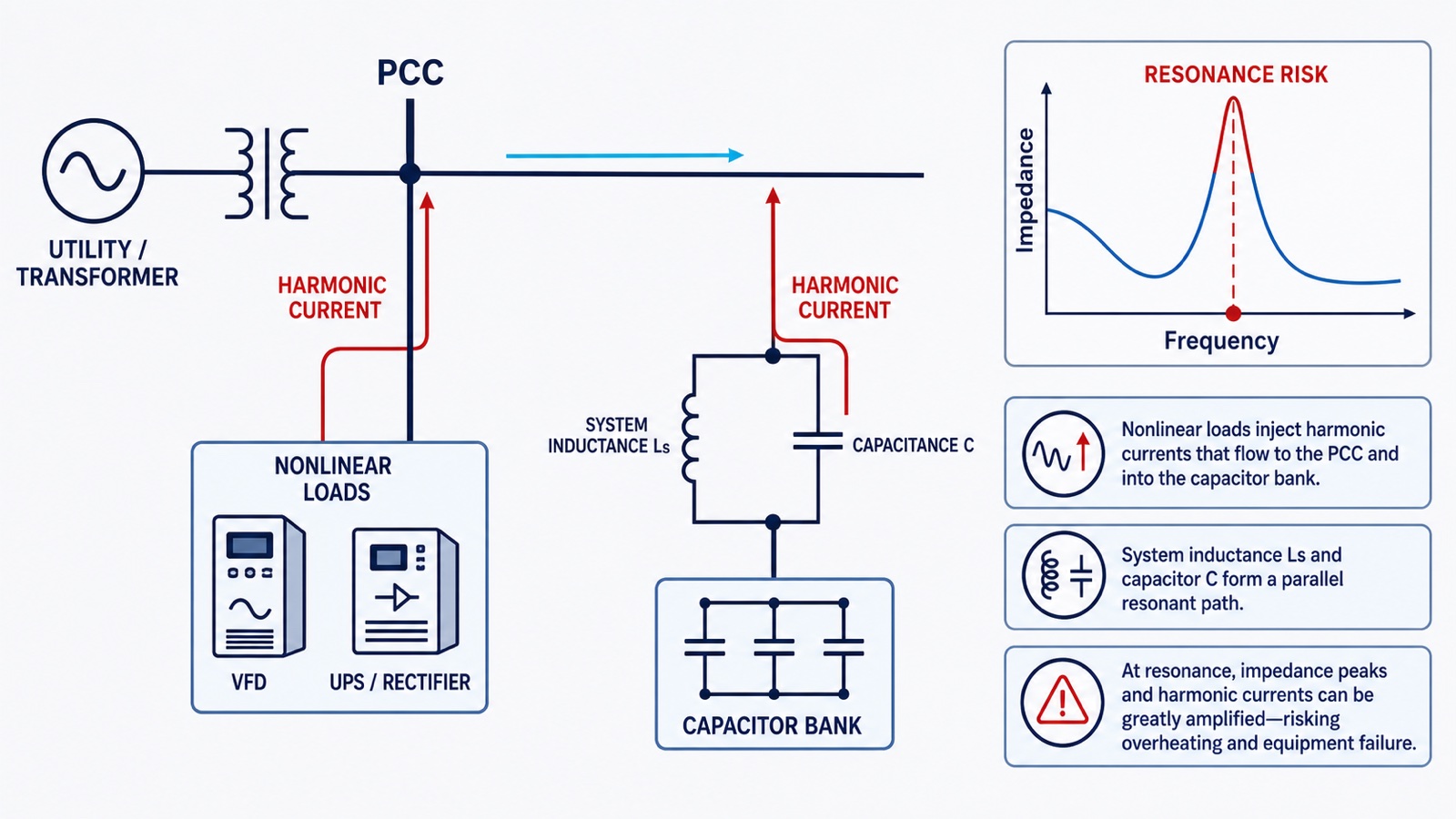
Because capacitor impedance falls at higher frequencies, harmonic current adds to the 50/60 Hz capacitor current. The RMS current can exceed the rating of capacitor elements, cables, fuses, contactors, and busbars. Extra current produces additional heat, accelerates dielectric aging, and shortens service life.
The supply transformer and grid behave mainly as an inductive source, while the capacitor bank is capacitive. Together they create a natural resonant frequency. If that frequency is close to a harmonic already present in the plant, the harmonic voltage and current can be magnified. A bank that previously operated normally may become unstable after extra capacitance or nonlinear load is added.
A first screening estimate for harmonic order is:
h ≈ √(Ssc / Qc)
where Ssc is the short-circuit power at the capacitor connection point and Qc is the installed capacitor rating, using consistent units. This estimate is useful for screening, but final selection should use actual network and harmonic data.
Harmonic losses raise the internal temperature of capacitors and reactors. A hot electrical room, clogged filter, undersized enclosure, loose termination, or failed fan compounds the problem. Temperature is a critical life factor: a bank may pass a basic kvar check yet still fail because its thermal environment was ignored.
Each switching event can create a high inrush current. Rapidly changing loads may force conventional contactor-switched steps to cycle too frequently. Worn contacts, welded contactors, fuse operation, and transient overvoltage can follow. Thyristor switching can improve response and reduce mechanical wear, but it does not remove the need for a harmonic and resonance assessment.
Capacitor terminal voltage rises when a series reactor is used, so the capacitor voltage rating must match the detuned-bank design rather than just the nominal system voltage. The reactor tuning factor must also keep the series resonant frequency below the dominant harmonic while meeting local design requirements. Copying a standard bank specification into a different network can create a new risk.
| Observed symptom | Likely electrical cause | First engineering check | Typical response |
|---|---|---|---|
| Bulging or leaking capacitor cans | Sustained overcurrent, overvoltage, or heat | Phase current, voltage, temperature, harmonic spectrum | Isolate damaged units; reassess duty and ventilation |
| Repeated fuse operation | Harmonic overload, failed element, or switching inrush | Fuse coordination and step current waveform | Correct fault, protection, and switching design |
| Reactor noise or overheating | Excess harmonic current, core saturation, loose assembly | Reactor temperature and current by harmonic order | Verify tuning, rating, airflow, and connections |
| High THDv after bank energizes | Parallel resonance amplification | Compare spectrum with steps off and on | Detune/redesign bank; mitigate source harmonics |
| Contactor damage | High inrush or excessive switching frequency | Switching event capture and operation count | Use capacitor-duty contactors or thyristor switching |
| Good kvar but poor reliability | Thermal/mechanical environment overlooked | Enclosure temperature, dust, torque, ventilation | Correct installation and maintenance conditions |
Document the single-line diagram, transformer ratings and impedance, capacitor step sizes, reactor data, conductor sizes, protection, and major nonlinear loads. Note whether failures correlate with production shifts, generator operation, solar inverter output, or particular capacitor steps.
Use a suitable power-quality analyzer at the point of common coupling and, where practical, at the capacitor feeder. Record voltage, current, kW, kvar, power factor, THDi, THDv, individual harmonic orders, unbalance, and switching events. Capture representative low-, normal-, and high-load periods rather than one convenient snapshot.
For definitions and measurement interpretation, see THDi vs THDv: What Is the Difference?.
If site procedures permit controlled switching, compare the harmonic spectrum with different bank steps connected. A sharp rise in a particular harmonic voltage or feeder current after a step is energized is an important resonance warning. This work should be performed by qualified personnel under an approved electrical safety procedure.
Check resonance for minimum and maximum system strength, different transformer or generator configurations, and each meaningful capacitor-step combination. A system can move through several resonant frequencies as steps change.
Review capacitor, reactor, fuse, contactor, cable, and enclosure ratings. IEEE 519 is commonly referenced for harmonic control at the point of common coupling; equipment loading and local compliance requirements must also be checked. Do not treat one THD number as the complete acceptance criterion.
| Site condition | Preferred starting point | Why |
|---|---|---|
| Stable kvar demand, moderate known harmonics | Detuned capacitor bank | Cost-effective fundamental kvar with resonance protection when correctly engineered |
| Rapidly changing inductive/leading kvar demand | Static Var Generator (SVG) | Fast, stepless bidirectional reactive-current compensation |
| Excess harmonic current is the main problem | Active Harmonic Filter (AHF/APF) | Injects compensating harmonic current according to measured demand |
| Harmonics and dynamic kvar both matter | AHF + SVG or ASVG | Separates or coordinates harmonic and reactive-current duties |
| High-voltage network with flicker/large dynamic demand | Project-specific STATCOM solution | Suitable for higher-power dynamic compensation after system study |
A Static Var Generator versus capacitor bank comparison helps distinguish slow, stepped kvar correction from fast electronic compensation. If the dominant issue is distorted current rather than kvar, review AHF versus SVG selection.
Consider a 400 V plant with multiple six-pulse drives and a conventional automatic capacitor bank. Operators report hot reactors and occasional fuse operation. Measurements show that the 5th harmonic voltage rises when the larger capacitor steps connect, while capacitor feeder RMS current increases well above its fundamental component.
The engineering team should not assume that replacing the failed capacitor with the same part will solve the cause. A more robust process is to:
This example reflects the recurring field pattern Elumotive engineers evaluate in industrial power-quality projects: the visible failure is at the capacitor bank, but the root cause is the interaction among the source impedance, nonlinear-load spectrum, compensation steps, and operating cycle. Shanghai Elumotive Technology evaluates low-voltage projects using the site's actual voltage, transformer data, harmonic spectrum, reactive-current trend, cabinet conditions, and required response. A final equipment rating must be based on those inputs; it should not be inferred from plant kVA, power factor, or THDi alone.
| Project input | Why it matters |
|---|---|
| Nominal voltage and frequency | Defines the compatible equipment platform and insulation duty |
| Transformer kVA, impedance, and operating configuration | Supports short-circuit strength and resonance assessment |
| Capacitor step kvar, rated voltage, and reactor tuning | Identifies loading and resonant-frequency risks |
| Harmonic spectrum and RMS current by phase | Supports AHF/APF compensation-current selection |
| Time-based kW, kvar, power factor, and unbalance | Supports SVG capacity and dynamic-response assessment |
| Ambient temperature, altitude, ventilation, and enclosure data | Supports thermal derating and cabinet design |
Elumotive's relevant solution families include cabinet-type Active Harmonic Filter systems and 400 V ASVG equipment. Exact current, voltage, enclosure, redundancy, and compensation settings should be confirmed against the current product datasheet and project conditions before quotation or publication of a project-specific parameter.
For a broader workflow, read How to Improve Power Factor in Industrial Plants.
Severe electrical or thermal stress can cause element failure and pressure buildup. Modern capacitors may include protective disconnection features, but these are not a substitute for correct harmonic, voltage, thermal, and protection design. Swollen or leaking units should be isolated and assessed by qualified personnel.
Its primary purpose is to shift the capacitor-reactor resonance below a problematic harmonic and limit harmonic current into the bank. A detuned bank is not generally an Active Harmonic Filter and should not be presented as removing all harmonic current from the network.
An SVG mainly provides fast reactive-current compensation. It does not automatically cancel harmonic current unless the selected product and control configuration explicitly include that capability. The existing bank still requires a resonance and loading assessment.
Temporary isolation may be necessary for safety after abnormal symptoms, but permanent removal can worsen power factor, increase current, or incur utility penalties. Diagnose the root cause and choose a properly engineered compensation method.
Provide the single-line diagram, voltage and frequency, transformer data, capacitor/reactor details, load list, time-based kW/kvar/power-factor data, THDi and THDv trends, harmonic spectrum by phase, operating scenarios, and target limits.
The interval depends on manufacturer guidance, duty, environment, and site rules. Routine checks commonly include visual condition, temperature, ventilation, fuse state, current balance, terminal tightness under approved procedures, and comparison with commissioning baselines.
Shanghai Elumotive Technology supplies power-quality solutions including Active Harmonic Filter (AHF/APF), Static Var Generator (SVG), and project-specific compensation systems. Send Elumotive your single-line diagram, transformer data, capacitor-bank details, harmonic measurements, and operating profile. We can help evaluate whether a detuned bank, AHF, SVG, ASVG, or combined approach fits the application.
Contact Elumotive for a project evaluation.