AHF acceptance testing for an active harmonic filter (AHF) or static var generator (SVG) is not accepted because its display shows “running.” This AHF acceptance testing review separates FAT, SAT and site commissioning evidence. A usable acceptance process must prove three different things: that the supplied equipment is built and configured as specified, that it is safely integrated into the site, and that it delivers the agreed result at a defined electrical boundary.
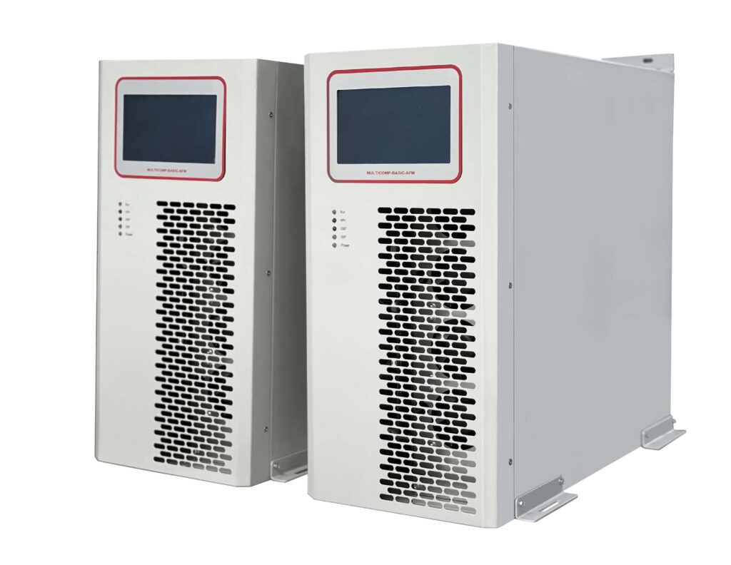
Quick answer: Factory acceptance testing (FAT) confirms the equipment, protection functions and documented configuration before shipment. Site acceptance testing (SAT) confirms installation, wiring, interfaces and safe functional operation after installation. Final performance commissioning must compare baseline and post-installation measurements at the agreed point, under stated operating conditions. A passed FAT does not by itself prove IEEE 519 compliance or a project-wide power-quality result.
These terms are sometimes used interchangeably, which creates avoidable disputes. They should be separated in the project specification.
A panel can pass FAT without ever seeing the customer’s transformer impedance, capacitor bank, generator mode or nonlinear load mix. Conversely, a site result may be poor even when the converter is healthy if CTs are installed at the wrong point, the filter is undersized, or the acceptance meter is measuring a different electrical boundary from the control system.
The first item in an acceptance plan is not a test instrument. It is a diagram.
Mark the following on the latest single-line diagram:
The controller may be designed to regulate a local feeder while the project contract sets a target at the PCC. Neither arrangement is automatically wrong, but the two boundaries must not be confused. IEEE 519-2022 describes the interface between sources and loads as the point of common coupling; the project specification and utility agreement determine whether and how that standard applies to a particular installation.
FAT must reflect the agreed equipment scope. It should not claim to reproduce a customer’s whole electrical system. Typical records include the following.
| Test item | Purpose | Evidence to retain |
|---|---|---|
| Nameplate, ratings and assembly | Confirms voltage, frequency, wiring form, capacity and enclosure match the order | Signed inspection record and nameplate photos |
| Hardware, firmware and parameter version | Establishes a reproducible configuration | Version export and approved parameter file |
| Internal functional checks | Confirms controller, HMI, sensors, fans and auxiliary supplies operate | Functional checklist and alarm log |
| Protection response | Verifies approved reaction to overcurrent, overtemperature, DC-bus abnormality or sensor fault | Test record, event codes and reset procedure |
| Communication and interlocks | Checks required protocols, dry contacts and external permits | I/O test record and communication map |
| Current capability test | Demonstrates the agreed factory capability within the test arrangement | Test method, duration, ambient condition and measured output |
| Module and bypass behavior | Confirms the specified architecture can isolate, alarm or continue as designed | Sequence record and operating procedure |
For an AHF, factory testing may demonstrate current injection, selected harmonic-order logic and limits under a controlled source/load arrangement. For an SVG, it may demonstrate leading and lagging reactive-current operation, response to setpoint changes and limit handling. The exact method depends on available factory equipment and should be agreed before the test, not improvised after the cabinet is built.
SAT begins after equipment installation, but before relying on the system for full performance. It is primarily an integration and safety check.
Verify incoming voltage, frequency, phase sequence and grounding arrangement. Confirm the panel breaker, cable size, protective conductor, isolation device and bypass arrangement agree with the approved drawings. Check cabinet clearances, ventilation route, ambient conditions and service access.
CT verification deserves a separate procedure. Confirm the intended location, phase mapping, polarity, ratio and secure termination. A CT must measure the current the control strategy expects to see. Never open-circuit an energized CT secondary. Compare phase current and phase relationship against an independent analyzer before enabling compensation.
For communications, verify not only that a protocol connects, but also that the correct tags, alarms, time synchronization and permissives work. An event history that lacks timestamps, operating mode or version information will be difficult to use during a later fault investigation.
A before-and-after comparison is valid only when it compares equivalent conditions. Record the measurement point, analyzer configuration, CT ratio, harmonic range, aggregation interval and timestamp. Record the load state as well: production line status, UPS mode, number of operating drives, charger concurrency, generator mode and capacitor-bank steps can all change the result.
IEC 61000-4-30:2025 defines methods for measurement and interpretation of power-quality parameters in AC supply systems. Where the contract references a measurement class or aggregation method, follow that requirement. A single screenshot at an unknown load level is not a defensible baseline.
For harmonic projects, retain fundamental current, harmonic RMS current, individual harmonic orders, THDi, TDD where applicable, voltage distortion and true power factor. THDi should not be used alone because its value changes with fundamental current. For SVG projects, retain kW, kvar, kVA, displacement and true power factor, voltage trend, unbalance where relevant, and the response to representative load steps.
A controlled sequence reduces risk and makes faults easier to isolate.
A project with generator or bypass operation should include those modes in the test plan. A system that behaves correctly on utility supply may see a different voltage response when source impedance changes on generator supply.
Consider an AHF installed at a manufacturing main bus. The contract requires a reduction in selected harmonic current at the bus under a stated production combination, plus alarm reporting to the site monitoring system. FAT confirms the ordered voltage class, 300 A current rating, approved parameter set, overtemperature trip behavior and communications. SAT confirms CT polarity, phase order, panel breaker, exhaust path and dry-contact mapping. Site commissioning then compares individual harmonic current and TDD at the named bus with the same production machines running before and after AHF enablement.
The acceptance report should state what the equipment achieved under that condition. It should not convert a result at one load state into a guarantee for every future expansion, generator mode or capacitor-bank configuration.
For related preparation, review our power-quality audit checklist and AHF installation and commissioning guide.
No. FAT can prove agreed equipment functions, but IEEE 519 assessments depend on the actual system, measurement boundary, demand current, voltage distortion and operating conditions at the site.
SAT itself can be completed during controlled installation and functional checks. Final performance acceptance should include the agreed representative load conditions, which may include high-load operation.
A controlled change should be documented and assessed against its effect on protection, communication and control performance. The project procedure should define whether functional or site-performance retesting is required.
A clear acceptance matrix prevents late-stage disagreement and creates useful records for future expansion. Send the technical specification, current single-line diagram, required operating modes and target measurements to Elumotive for an initial FAT, SAT and commissioning review.


Leave a Comment