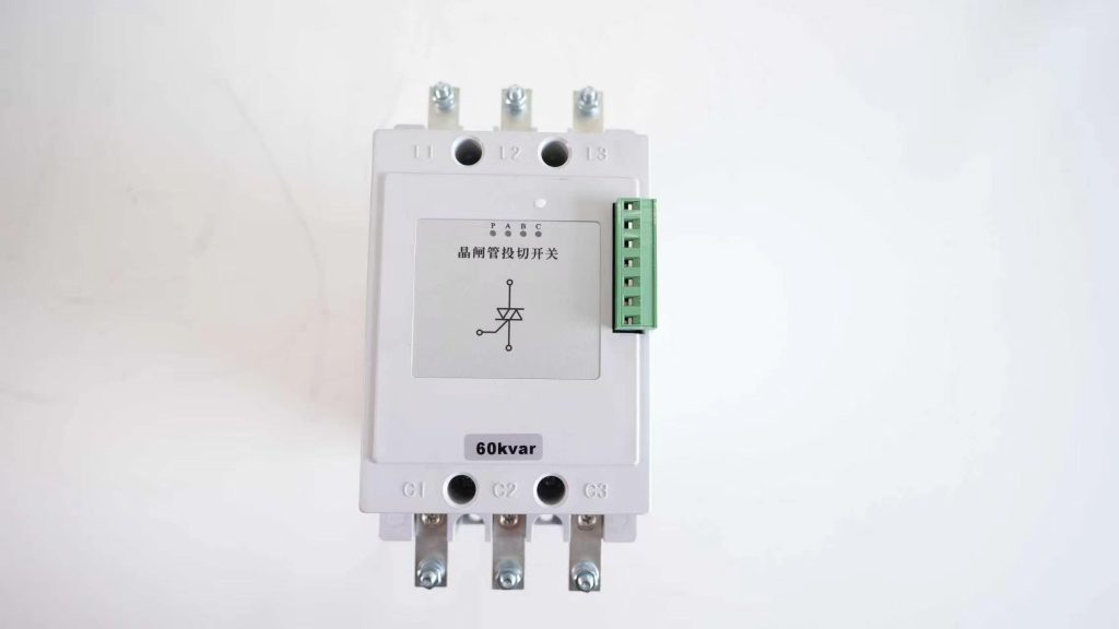
Model: SET-TSC-20F / 30F / 40F / 50F / 60F
SET-TSC-F split phase thyristor switch for AC 220V star-connected capacitor banks, with independent A/B/C zero-crossing control and 20–60 kVAR options.
The SET-TSC-F split phase thyristor switch provides separate A-, B- and C-phase control for star-connected capacitor stages. It helps a split-phase reactive-power controller respond to unequal phase demand without forcing all three phases to switch together.
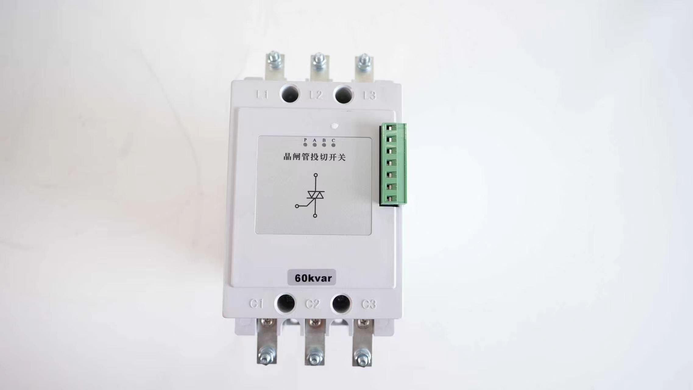
Separate KA, KB and KC control signals allow the compensation controller to connect A-, B- or C-phase capacitor branches according to each phase’s measured reactive requirement.
Equipotential zero-crossing technology targets voltage-zero turn-on and current-zero turn-off, reducing inrush current and overvoltage during frequent capacitor switching.
High-power anti-parallel thyristor modules provide arc-free operation without contact bounce, audible switching noise or routine contact replacement.
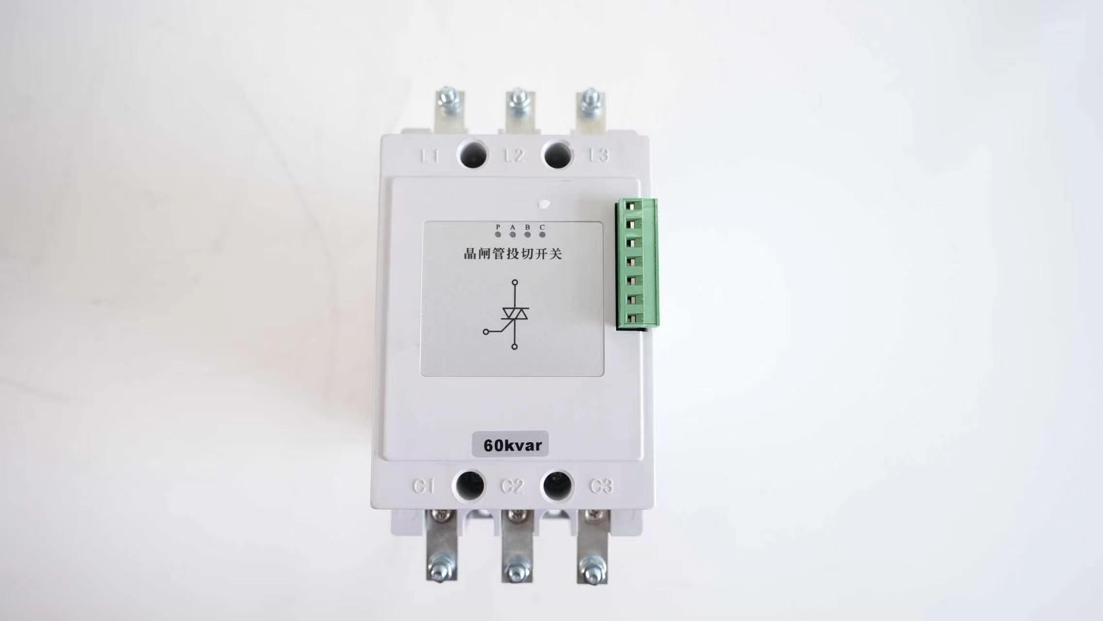
L1, L2 and L3 connect to the system phases; C1, C2 and C3 connect to the corresponding star-connected capacitor branches. The neutral point is wired according to the capacitor-bank design. The controller sends separate low-voltage commands for phases A, B and C.
This structure is suitable for commercial buildings, municipal distribution, mixed single-phase production loads and other 0.4 kV networks where phase power factors differ substantially.
Use a split-phase reactive-power controller with independent A, B and C outputs. Confirm the control voltage, polarity and common terminal before commissioning.
Match each phase branch to the specified voltage and kVAR. Where harmonics are present, coordinate detuned reactors and capacitor voltage rating with the system study.
Provide phase fuses, suitable conductors, ventilation and clearances. Semiconductor losses make cabinet thermal design essential for continuous service.
| Product family | SET-TSC-F split phase thyristor switch |
|---|---|
| Rated phase voltage | AC 220 V |
| Rated frequency | 50 Hz |
| Control voltage / current | DC 5–12 V / 12 mA |
| Connection | Split-phase compensation, Y-connected capacitor branches |
| Rated total capacity | 20 / 30 / 40 / 50 / 60 kVAR |
| Voltage distortion limit | ≤5% |
| Switching response | Less than 20 ms |
|---|---|
| Thyristor reverse voltage | 1800 V class |
| Overall dimensions | 190 × 118 × 206 mm |
| Mounting dimensions | 179 × 35 mm |
| Operating temperature | −25°C to +45°C |
| Relative humidity | ≤90%, good ventilation required |
| Installation altitude | ≤2000 m |
Verify phase sequence, capacitor neutral arrangement, fuse continuity, controller output polarity and the kVAR value of every branch. During a factory test without capacitors, the operation manual recommends an incandescent lamp as a temporary dummy load. Maintain at least 30 mm between adjacent modules.
If one phase refuses to operate, check its KA/KB/KC command, control-voltage polarity, phase fuse, capacitor continuity, heat-sink temperature and harmonic condition.
| Model | Matched total capacitor capacity | Connection | Dimensions |
|---|---|---|---|
| SET-TSC-20F | Up to 20 kVAR | Three independent Y branches | 190 × 118 × 206 mm |
| SET-TSC-30F | Up to 30 kVAR | Three independent Y branches | 190 × 118 × 206 mm |
| SET-TSC-40F | Up to 40 kVAR | Three independent Y branches | 190 × 118 × 206 mm |
| SET-TSC-50F | Up to 50 kVAR | Three independent Y branches | 190 × 118 × 206 mm |
| SET-TSC-60F | Up to 60 kVAR | Three independent Y branches | 190 × 118 × 206 mm |
SET-TSC-G switches one three-phase delta-connected capacitor stage with a common command. SET-TSC-F provides three independent commands for star-connected A-, B- and C-phase capacitor branches.
Yes. The SET-TSC-F is intended for independent phase control when used with a compatible split-phase compensation controller and correctly wired star-connected capacitor branches.
Zero-crossing control is designed to suppress the impact inrush associated with uncontrolled capacitor energization. Actual performance still depends on residual capacitor voltage, wiring, system harmonics and correct commissioning.
The module includes harmonic-aware protection, but the capacitor bank must also be designed for the actual harmonic environment. A detuned reactor and a higher capacitor voltage rating may be required after system assessment.
SET can coordinate the split-phase controller, SET-TSC-F switch, capacitors, reactors, fuses and thermal design for an unbalanced low-voltage network.