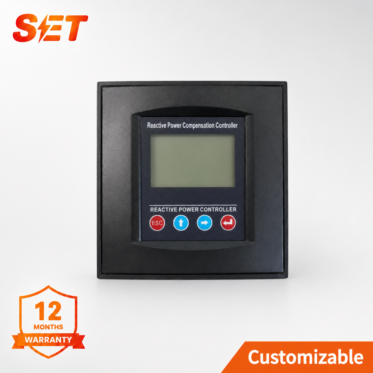
Model: SET-JKWC-24 Split-Phase
SET-JKWC-24 split-phase reactive power compensation controller for AC 220V systems, with 24 assignable Y/Δ outputs, per-phase monitoring and harmonic protection.
The split-phase SET-JKWC-24 controller measures Phase A, B and C independently and controls Y-type, Δ-type or combined Y+Δ capacitor stages. It is designed for installations where single-phase loading creates unequal reactive-power demand that a common three-phase controller cannot correct precisely.
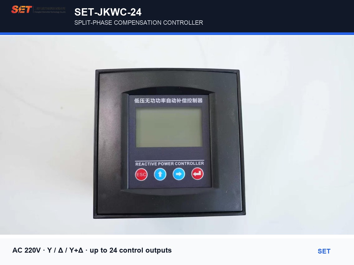
Monitors Phase A/B/C voltage, current, power factor, active power and reactive power rather than relying on one common value for the whole system.
Channels can be assigned to A, B, C or Δ capacitor groups. This supports Y-type split-phase compensation, Δ-type common compensation, or a combined Y+Δ panel.
Measures voltage/current THD and individual odd harmonics from the 3rd through the 21st on each phase. Adjustable limits help block unsafe switching conditions.
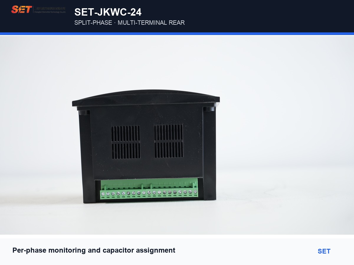
Each output can be configured for an A-phase, B-phase, C-phase or common Δ capacitor step. The controller stores the channel type and capacity, then calculates switching decisions from the measured reactive power. Unused outputs can be disabled by setting their capacity to zero.
| Model / series | SET-JKWC-24, split-phase compensation |
|---|---|
| Application | 0.4 kV, 50 Hz low-voltage distribution |
| Supply / sampling voltage | AC 220 V ±20%, phase to neutral |
| Sampling current | 0–5 A or 0–1 A CT secondary |
| Frequency | 50 Hz ±5%; adaptive algorithm for 45–55 Hz signals |
| Compensation modes | Y-type, Δ-type, Y+Δ combined |
| Control outputs | Up to 24 channels |
| Display | 128×64 dot-matrix LCD, Chinese / English |
| Voltage accuracy | ±0.5% |
|---|---|
| Current accuracy | ±0.5% |
| Active / reactive power | ±1.0% |
| Power-factor accuracy | ±1.0% |
| Operating temperature | −25°C to +65°C |
| Humidity | ≤90% RH at 20°C |
| Altitude | ≤2500 m |
| Dimensions / cutout | 144×144×110 mm / 138×138 mm |
The automatic display cycles through capacitor status, per-phase electrical values, THD, temperature when fitted, and harmonic data. When a grid value exceeds its set limit, the relevant item is highlighted for faster commissioning and fault finding.
The split-phase controller uses AC 220 V phase-to-neutral supply and sampling. The manual requires the three phase-voltage and current signals to be correctly paired by phase. Set the CT ratio, Y/Δ channel allocation and every capacitor-step value before enabling automatic control.
Use 1.5 mm² single-core copper wire for voltage/power connections and 2.5 mm² copper wire for CT current circuits. Keep current wiring short and route measurement signals away from high-current conductors.
A common controller switches three-phase Δ capacitor stages together. The split-phase version measures each phase and can switch A, B or C phase stages independently, while still supporting common Δ steps in the same panel.
Yes. The controller supports Y-type, Δ-type and Y+Δ combined compensation. Each output channel can be assigned to A, B, C or Δ and given its own capacity value.
Yes. The documented options are DC 12 V / 40 mA level output and 5 A / AC 220 V relay contact output. Specify the required output version when ordering.
Up to 24 control outputs are supported. The number assigned to split-phase and common compensation is configured according to the panel design.
SET can help define the Y/Δ split, output hardware, CT ratio, switching sequence and matching capacitor/reactor configuration for an unbalanced low-voltage network.