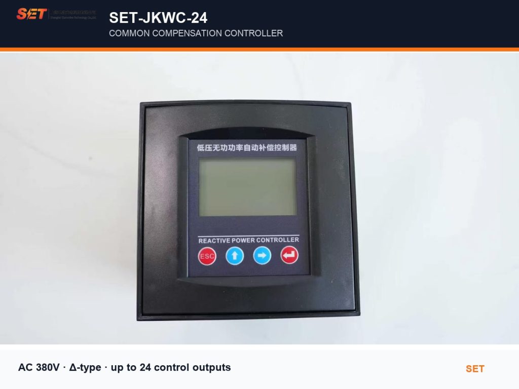
Model: SET-JKWC-24 Common
SET-JKWC-24 common reactive power compensation controller for AC 380V capacitor banks, with up to 24 outputs, harmonic monitoring and configurable protection.
SET-JKWC-24 combines reactive-power control, electrical measurement and harmonic supervision in one 144 mm panel controller. Designed for 0.4 kV, 50 Hz low-voltage distribution systems, it manages common three-phase capacitor steps using true reactive-power sampling to reduce hunting and unnecessary switching.
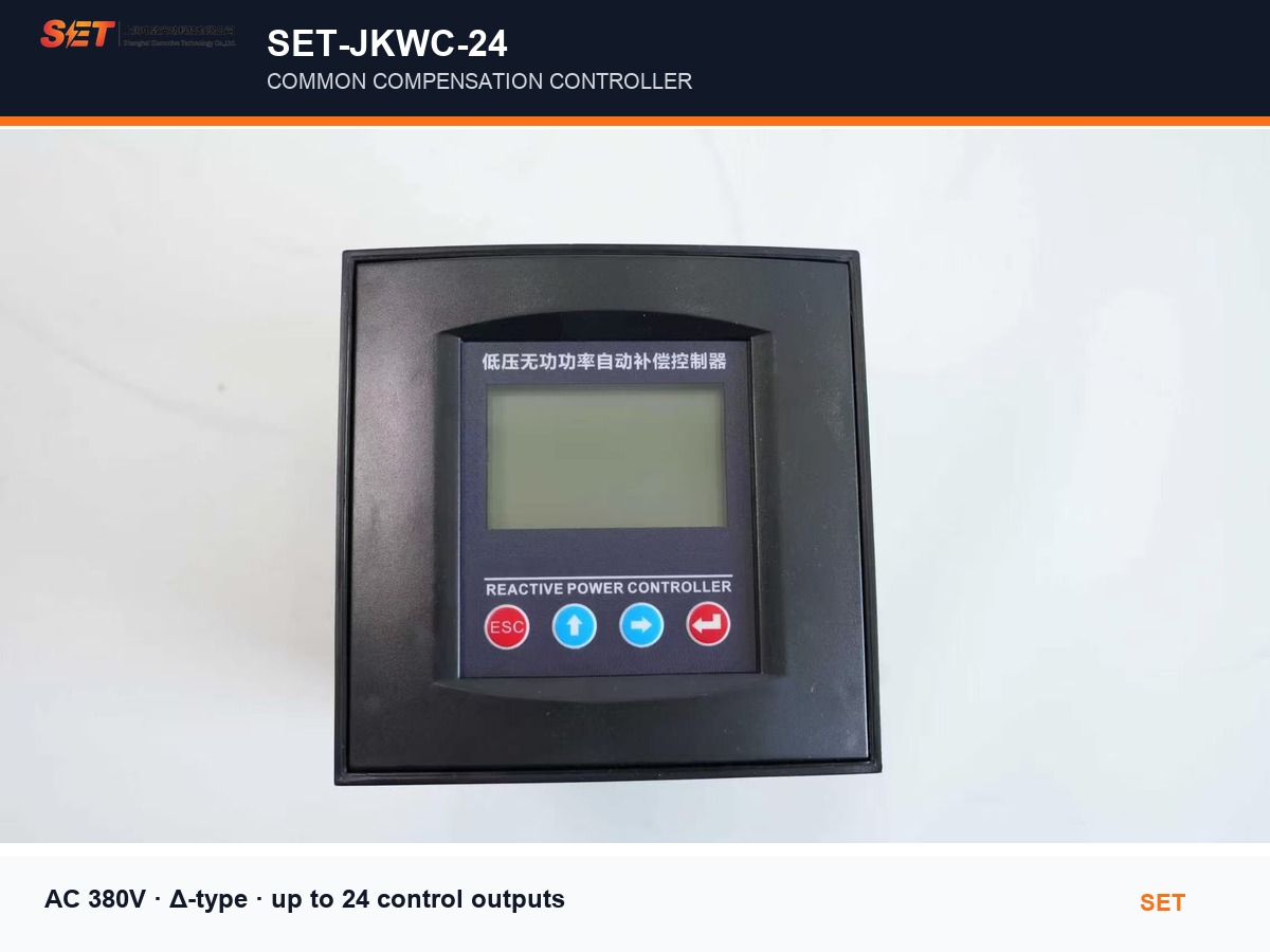
Displays voltage, current, power factor, active power, reactive power and system frequency. Operators can also review capacitor-step status directly from the LCD.
Reactive-power sampling and configurable switching thresholds help prevent repetitive switching around the target power factor. Capacitor capacity and step ratio can be set for the actual bank.
Monitors voltage and current THD plus individual 3rd through 21st odd harmonics. Adjustable THD limits can inhibit capacitor switching when the network condition is unsuitable.
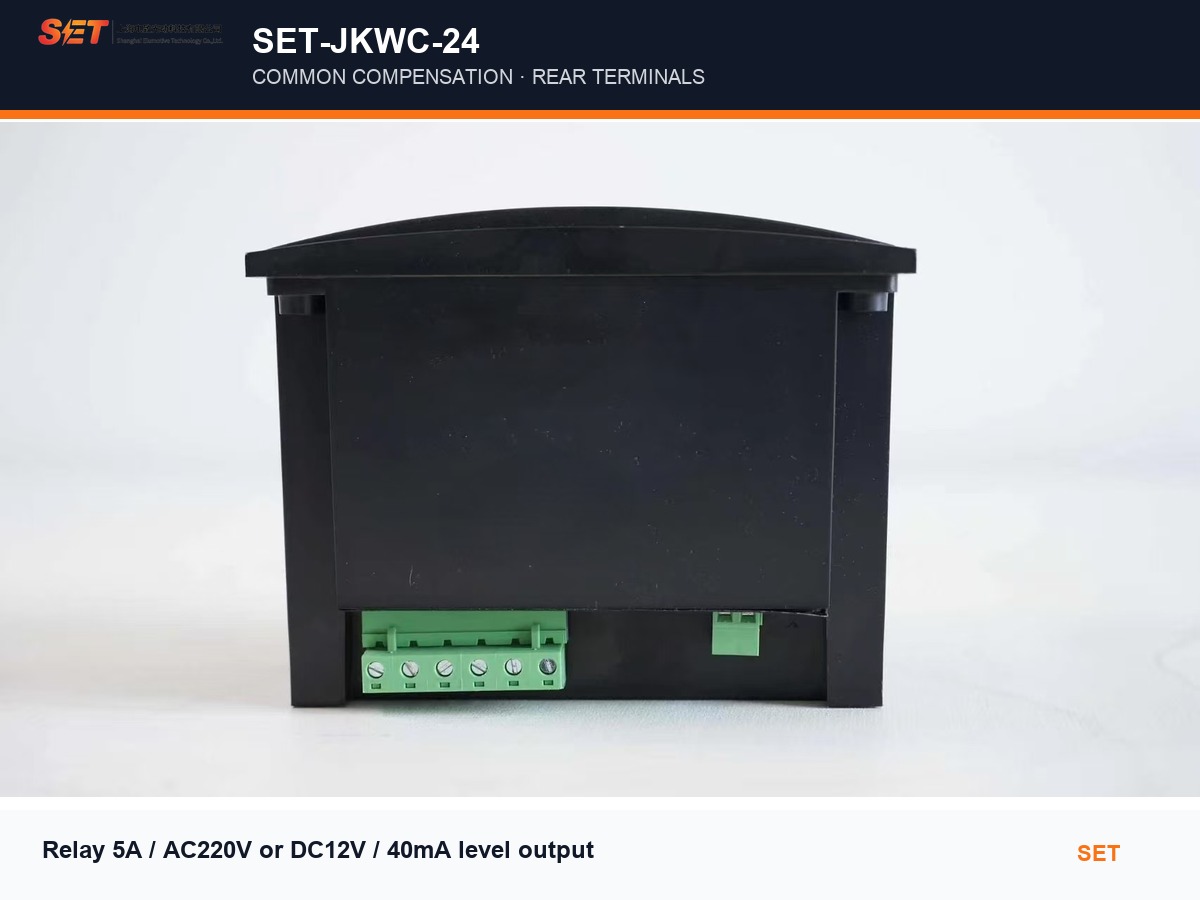
SET-JKWC-24 is available with either low-voltage level outputs for compatible switching devices or relay contacts for conventional contactor-based capacitor banks. The selected output form must match the actual control circuit.
| Model / series | SET-JKWC-24, common compensation |
|---|---|
| Application | 0.4 kV, 50 Hz low-voltage distribution |
| Supply / sampling voltage | AC 380 V ±20% |
| Sampling current | 0–5 A or 0–1 A CT secondary |
| Frequency | 50 Hz ±5%; adaptive algorithm for 45–55 Hz signals |
| Compensation mode | Δ-type common compensation |
| Control outputs | Up to 24 channels |
| Display | 128×64 dot-matrix LCD, Chinese / English |
| Voltage accuracy | ±0.5% |
|---|---|
| Current accuracy | ±0.5% |
| Active / reactive power | ±1.0% |
| Power-factor accuracy | ±1.0% |
| Operating temperature | −25°C to +65°C |
| Humidity | ≤90% RH at 20°C |
| Altitude | ≤2500 m |
| Dimensions / cutout | 144×144×110 mm / 138×138 mm |
Protection thresholds, CT ratio, target power factor, capacitor capacity, step ratio and switching times are configurable from the front panel. The controller indicates overvoltage, undervoltage, phase loss and other limit conditions on the display.
For the common-compensation version, the manual specifies sampling from two line voltages and one current signal with the correct phase relationship. Set the CT ratio and every capacitor-step value before automatic operation. Voltage conductors should use 1.5 mm² single-core copper wire; CT current wiring should use 2.5 mm² copper wire and be kept short.
Installation, testing and maintenance must be carried out by qualified electrical personnel. Short-circuit the CT secondary before disconnecting or replacing the controller.
Yes. Select the correct hardware version: Type B provides 5 A / AC 220 V relay contacts, while Type A provides DC 12 V / 40 mA level outputs. The order configuration must match the cabinet control circuit.
Yes. It measures voltage/current THD and the 3rd, 5th, 7th, 9th, 11th, 13th, 15th, 17th, 19th and 21st harmonic content. These readings support commissioning and configurable harmonic protection.
The platform supports up to 24 control channels. Unused channels can be disabled by setting their capacity to zero.
Use the split-phase version when each phase must be measured and compensated independently, or when a cabinet combines Y-type and Δ-type capacitor steps. The common version on this page is intended for Δ-type common three-phase compensation.
Our engineers can help match the controller output type, CT ratio, capacitor steps, switching device and reactor configuration to your low-voltage compensation cabinet.