

Photovoltaic Site: Reactive Power Compensation Project
SET ‘s high-side sampling, low-side compensation reactive power compensation scheme offers a technically sound and efficient solution to the common power-factor degradation problem in PV-connected sites.
Project Summary and Replication Value
Project Summary
SET designed a high-side sampling, low-side compensation structure for a factory in Xi’An Province. The factory adopted grid-connected PV, causing its power factor to drop to 0.77 and incurring monthly penalties exceeding RMB 10,000. SET’s solution measures reactive current on the high-voltage (HV) side and performs compensation on the low-voltage (LV) side using a 200-kvar Static Var Generator (SVG). Once commissioning, the HV-side reactive power remained stable near 0 kvar, and the power factor rose to 0.94. This eliminated penalties and even earned utility rebates. This scheme adapts easily to various PV-equipped sites. It requires no major modification to existing PV equipment and integrates seamlessly with legacy compensation systems. It improves grid power quality, reduces line losses, protects users from financial penalties, and enhances the overall profitability of PV investments, delivering both economic and grid-stability benefits.
Reported Application Results
By deploying the high-side sampling, low-side compensation scheme with the 200-kvar SVG, the project achieved the following results:
| Parameter | Before Compensation | After Compensation |
|---|---|---|
| HV-side reactive power (night) | ≈20 kvar | Stable near 0 kvar |
| HV-side reactive power (daytime) | >60 kvar | Stable near 0 kvar |
| Power factor | 0.77 | 0.94 |
| Utility penalty | Up to >RMB 10,000/month | No penalty; earned rebates |
Power Quality Issues and Their Impact
Power Factor Degradation After PV Integration
According to the Regulations on Power Factor Adjustment Charges, general industrial users must maintain a monthly average power factor above 0.90; otherwise, penalties apply. Traditionally, factories use switched capacitor banks for reactive compensation. The grid supplies a large amount of active power. Although capacitor compensation has limitations, the remaining reactive power is negligible relative to the total active power drawn from the grid. Therefore, the power factor can still meet the 0.90 threshold. Installation of PV generation, however, supplies a significant portion of the active power, drastically reducing the active power drawn from the grid. The residual reactive power left uncompensated by capacitor banks becomes substantial compared with the reduced grid-supplied active power. Transformers and transmission lines also consume reactive power, further increasing net reactive power on the HV side. Consequently, the overall power factor drops sharply, leading to heavy utility penalties and financial losses.
Key Impacts
| Issue | Cause | Impact |
|---|---|---|
| Power factor degradation | PV supplies most active power; grid-sourced active power decreases sharply | Utility penalties |
| Capacitor compensation insufficiency | Stepped compensation and slow response | Residual reactive power remains uncompensated |
| Transformer and line reactive power | Intrinsic reactive consumption of transformers and lines | Additional reactive demand on HV side |
Solution
Principle of the High-Side Sampling, Low-Side Compensation Scheme
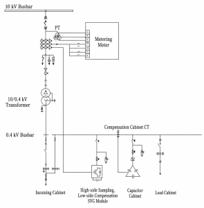
Utilities typically perform revenue metering on the HV side. Their reactive-power measurements include not only the reactive power drawn by LV loads but also the reactive consumption of transformers and transmission lines. Conventional LV-side compensation only addresses load-generated reactive power, leaving transformer and line reactive demand uncompensated.
For PV sites, this transformer and line reactive component cannot be ignored. The proposed scheme places the sampling point on the HV inlet while performing compensation on the LV side. This approach simultaneously corrects reactive power on both the HV and LV sides. Compared with traditional HV reactive compensation equipment, this scheme costs significantly less, installs more easily, and maintains more simply.
Core Equipment Selection: SVG Static Var Generator
At PV sites, active power consumption from the grid is minimal, so reactive compensation must achieve very high precision. Conventional capacitor banks, with stepped compensation and slow response, cannot meet this requirement; SVG is required.
The SVG operates on a voltage-source inverter principle. It uses IGBTs to control the magnitude and phase of the inverter output voltage, generating a counter-phase reactive current that cancels the grid’s reactive current. Because IGBT switching frequencies reach tens of kHz, the SVG responds in ≤5 ms and achieves compensation accuracy of ≥99%.
Deployment
Sampling Methods
The project offers two HV-side sampling options:
- Direct HV current sampling – The SVG directly samples the HV current. Based on transformer parameters, it sets the voltage-current phase angle, calculates HV-side reactive power, and then the LV-side SVG compensates accordingly.
- Multifunction meter sampling – A multifunction meter is installed on the HV side to measure secondary voltage and current signals. The meter calculates reactive power and transmits the value via RS485 communication to the SVG for compensation.
Installation and Coordination without Production Interruption
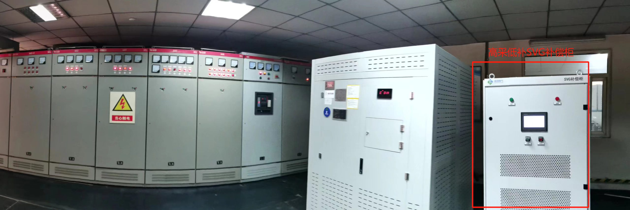
Installers can wall-mount the SVG, integrate it into cabinets, or house it in containerized outdoor enclosures, making the scheme adaptable to various site conditions. The high-side sampling, low-side compensation approach operates in parallel with existing compensation devices. The required capacity primarily depends on the measured residual reactive power on the HV side. During installation, the existing compensation controller should not sample the SVG’s compensation current. This allows the original system to continue operating normally while the SVG handles residual reactive power.
Advantages of the Structure
The architectural choice, separating the sampling point on the HV side from the compensation point on the LV side, offers several engineering benefits.
- High-precision compensation – The SVG responds in ≤5 ms and delivers ≥99% accuracy, tracking rapid changes in reactive demand typical of PV sites.
- Cost-effectiveness – Compared with traditional HV reactive compensation equipment, this scheme costs substantially less, installs more easily, and maintains more simply.
- Flexible deployment – The SVG supports wall-mounting, cabinet integration, or outdoor container housing.
- Full coverage of reactive sources – By sampling on the HV side, the system compensates for reactive power generated by LV loads, transformers, and cables.
Frequently Asked Questions
Q: Why does power factor drop after PV grid connection?
A: PV supplies a large share of active power, significantly reducing grid-supplied active power. Residual reactive power becomes proportionally large, while transformers and lines add further reactive consumption on the HV side.
Q: How does high-side sampling, low-side compensation differ from conventional LV compensation?
A: Conventional LV compensation addresses only load-generated reactive power. This scheme samples on the HV side and compensates on the LV side, correcting reactive power from both sides.
Q: Why must SVG be used instead of capacitors?
A: At PV sites, grid-supplied active power is minimal, so compensation must be highly accurate. SVG provides fast and accurate compensation with ≤5 ms response and ≥99% accuracy.
Q: Can the scheme operate alongside existing compensation equipment?
A: Yes. The SVG can be added to the existing system. Proper installation ensures the existing controller does not sample the SVG’s compensation current.