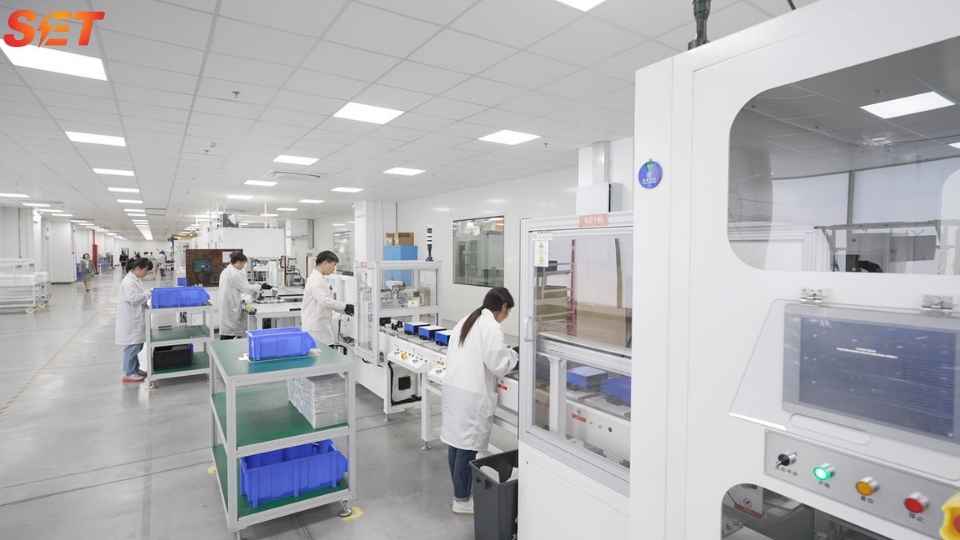
Semiconductor fab power quality directly affects yield, equipment availability and production recovery. A voltage sag lasting a fraction of a second can stop a process tool, trip a vacuum pump or reset a control system. Harmonic current from variable-speed drives, UPS systems and switched-mode power supplies can heat transformers and distort shared buses. The correct strategy combines equipment immunity, selective ride-through, harmonic control and event monitoring instead of relying on one facility-wide device.
Quick answer: map each critical tool and utility to its disturbance sensitivity, then protect the weakest layer. Use SEMI F47-aligned procurement and testing for tool voltage-sag immunity, UPS or dynamic voltage support for controls that cannot tolerate interruption, active harmonic filters (AHFs) for nonlinear current, and SVGs for rapidly changing reactive power or imbalance. Validate the result with synchronized power-quality and tool-event data.
A semiconductor process is a chain. Lithography, deposition, etch, implant, clean, metrology, vacuum, gases, cooling water and factory automation must remain coordinated. A tool may ride through a sag while its chiller, exhaust controller or robot trips, producing the same lost wafer lot. The electrical study must therefore include sub-fab and facility systems, not only the tool mainframe.
Production loads also vary by recipe and equipment state. RF generators, heaters, pumps and motion systems can change within a cycle, while large HVAC and chilled-water drives follow environmental demand. Thousands of electronic loads make aggregate behavior difficult to predict from nameplates. Trend data at the utility PCC, main switchboards, tool groups and sensitive auxiliary panels.
| Disturbance | Typical consequence | Evidence required | Control layer |
|---|---|---|---|
| Voltage sag | Contactor drop-out, drive trip, control reset | Depth, duration, phase pattern, tool alarm | Equipment immunity, UPS/DVR, protection review |
| Interruption | Process abort and long restart | Transfer time, stored energy, sequence logs | UPS, generator, redundant feed |
| Harmonics | Heating, resonance, nuisance alarms | Individual orders, THDi/TDD, THDv, temperature | Source design, AHF, passive/hybrid filter |
| Reactive power | Higher current and voltage variation | kvar, displacement PF, load cycle | SVG or coordinated capacitors |
| Unbalance | Motor heating and DC-link ripple | Voltage/current sequence components | Load balancing, four-wire SVG/AHF |
A voltage sag is a reduction in RMS voltage for a limited duration. Its impact depends on remaining voltage, duration, affected phases, phase-angle jump and the point on the load cycle. A 70% remaining-voltage event on one phase can disturb a three-phase drive differently from a balanced event. Two tools connected to the same bus may respond differently because of internal power supplies, contactors and control settings.
SEMI F47 defines minimum voltage-sag immunity and test requirements for semiconductor processing, metrology and automated test equipment. It is an equipment immunity specification, not a promise that the facility voltage will remain above its curve. Procurement should require the applicable test report, supported configuration and identification of subsystems that were included.
SEMI’s 2025 voltage-sag immunity workshop noted that fabs still experience downtime despite wide use of F47. That supports a layered approach: improve tool immunity, identify noncompliant auxiliaries, harden critical control circuits and apply facility mitigation only where the residual risk justifies it.
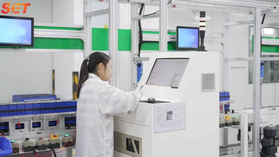
Local ride-through is often more economical than protecting an entire megawatt bus. A small UPS for controls can prevent a reset while motor kinetic energy carries a short event. A drive with a DC-bus ride-through or flying-start function may restart without stopping the process. These measures must respect emergency-off and safety logic; keeping an unsafe subsystem energized is not resilience.
Common nonlinear sources include six-pulse VFDs, UPS rectifiers, RF power supplies, switch-mode control supplies and LED lighting. Modern active-front-end equipment may have low input distortion at rated load, but the aggregate spectrum changes with recipes, partial loading and equipment mix. Measure individual harmonic amperes and voltage harmonics over production cycles. THDi alone can be misleading at light load.
At the PCC, evaluate TDD and individual orders where IEEE 519 criteria apply. Internally, check transformer and cable heating, neutral current, capacitor stress and sensitive-tool voltage distortion. An AHF should be located where it prevents harmful current from using shared capacity. Our TDD vs THDi article and active vs passive filter guide explain the compliance and equipment choices.
Fab utility systems contain many motors and transformers, while electronic process loads may operate near unity displacement power factor. The net kvar can change as chillers, pumps and air handlers stage. Fixed capacitor banks may overcompensate at light load and can resonate with the supply at harmonic frequencies. Detuned banks reduce resonance risk but remain stepped devices.
An SVG follows rapid kvar changes without capacitor switching and can absorb leading as well as supply lagging current. It is useful where power factor or bus voltage moves with production states. If the main issue is distortion rather than fundamental kvar, choose an AHF or a combined solution. Do not spend SVG current capacity on harmonics unless the product is designed and rated for both functions.
A process bay reports six tool trips in three months. The main incomer shows THDv of 3.2%, THDi varying from 8% to 24% and displacement power factor between 0.86 and 0.97. Event records show four trips coincided with utility voltage sags, one with a capacitor-bank switching transient and one with an internal VFD fault. Installing a large AHF alone would not solve five of the six events.
The correct plan separates causes. Tool and subsystem immunity is reviewed for the sag events; critical controls receive local ride-through. The capacitor bank and transformer impedance are modeled for switching and resonance, with an SVG or revised detuned bank considered for variable kvar. The VFD fault is addressed at equipment level. Harmonic mitigation is sized only after comparing harmonic amperes with internal thermal limits and PCC requirements.
A power-quality monitor should retain waveform captures for triggered events and long-term trends for RMS, unbalance, flicker and harmonics. Set thresholds from known tool sensitivity and applicable standards rather than generic defaults. Review nuisance alarms so the system remains trusted. Store event context: switchgear state, generator mode, production recipe and compensation status.
| Priority | Action | Why it comes first |
|---|---|---|
| 1 | Correct tool and control immunity gaps | Targets the weakest component directly |
| 2 | Coordinate protection and transfer settings | Prevents avoidable trips and long recovery |
| 3 | Add local UPS/DC ride-through | Protects high-value controls with limited kVA |
| 4 | Apply AHF/SVG at shared buses | Reduces recurring distortion or kvar current |
| 5 | Install facility-scale voltage support | Used when common exposure and economics justify it |
Facility-scale dynamic voltage restorers, UPS systems or alternate feeds can protect many tools, but their ratings and stored energy grow quickly. Quantify annual sag exposure, expected tool trips, wafer loss, recovery labor and production delay. Compare that risk cost with the lifecycle cost and coverage of each mitigation layer.
No. It defines minimum sag-immunity and test requirements for covered equipment. Events below the specified curve, untested phase patterns, configuration differences or vulnerable external facilities can still cause a trip.
An AHF reduces harmonic and, depending on design, reactive or unbalance current. It does not supply sustained active power during an upstream voltage sag. Sag ride-through needs equipment immunity, stored energy or voltage-restoration technology.
Use a hierarchy: PCC, major buses and selected critical tool groups. Permanent monitors at common points plus portable instruments for diagnosis usually provide a practical balance. All devices should share accurate time.
For a semiconductor fab power quality review, contact Elumotive with the one-line diagram, event files, load and kvar trends, harmonic spectra, capacitor details and tool trip history. We can then separate AHF, SVG and ride-through requirements into measurable project targets.

