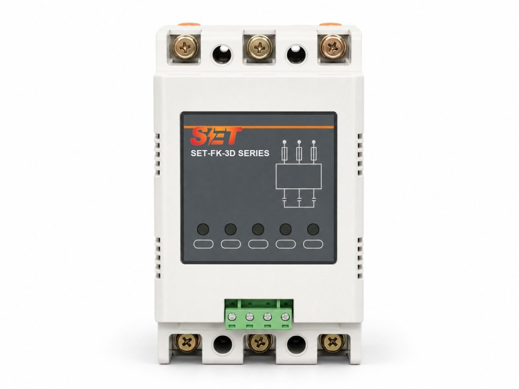
Model: SET-FK-3D/20-50
SET-FK-3D three-phase intelligent composite switch for AC 380V capacitor-bank switching, 20-50 kVAR, with zero-voltage closing, zero-current opening and <100ms response.
Three phase composite switch SET-FK-3D combines thyristor switching and a latching relay for fast, low-loss capacitor-bank control in AC 380V automatic power-factor correction systems. It is built for frequent, reliable step switching.
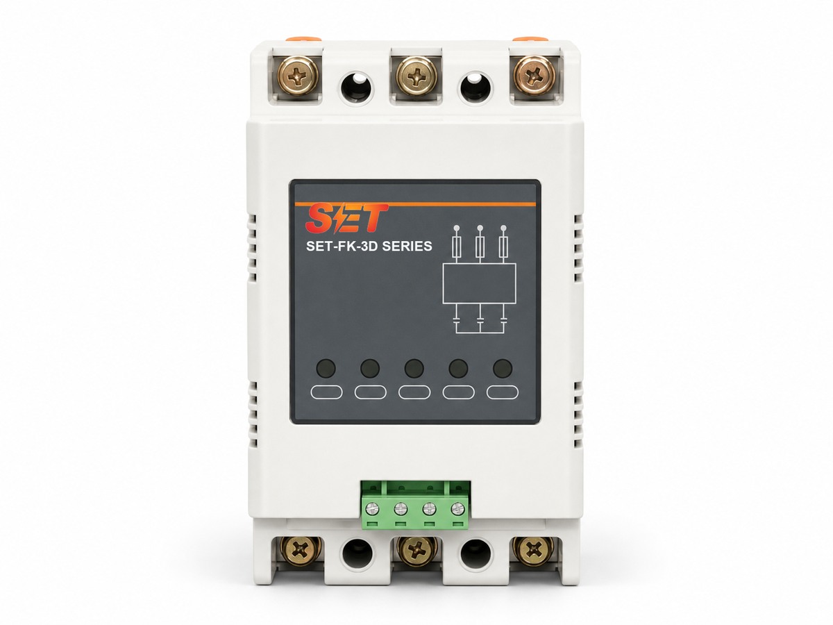
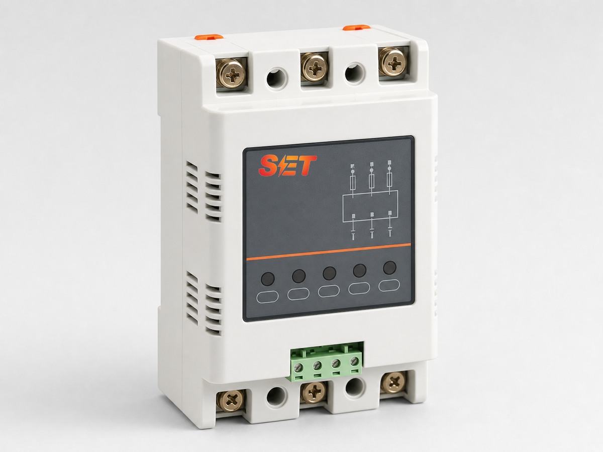
SET-FK-3D combines semiconductor switching with a latching relay in one compact device. The thyristor stage selects the optimum point on the AC waveform so the capacitor step closes near zero voltage and opens near zero current. After the transient is controlled, the relay carries the steady current with very low operating loss.
This hybrid architecture is designed for automatic power-factor correction panels that require smoother capacitor switching than a conventional contactor, without the continuous conduction loss of a fully electronic switch.
The APFC controller sends a low-power DC 5-12V switching command to the selected capacitor step.
The electronic stage identifies the suitable waveform point, reducing switching inrush and preventing contact arcing.
The latching relay maintains the capacitor connection efficiently and opens near zero current when compensation is no longer required.
Zero-voltage closing and zero-current opening reduce the severe transient current normally associated with capacitor switching.
The electronic transition protects the switching point and helps avoid contact burning, welding and repetitive mechanical impact.
Once switched, the latching relay carries the continuous load, limiting heat generation inside the compensation cabinet.
A response time below 100ms supports automatic capacitor steps in installations with changing reactive-power demand.
One integrated module replaces a more complex combination of switching and holding devices, simplifying cabinet wiring.
Front indicators provide a clear view of power, phase operation and fault status during commissioning and maintenance.
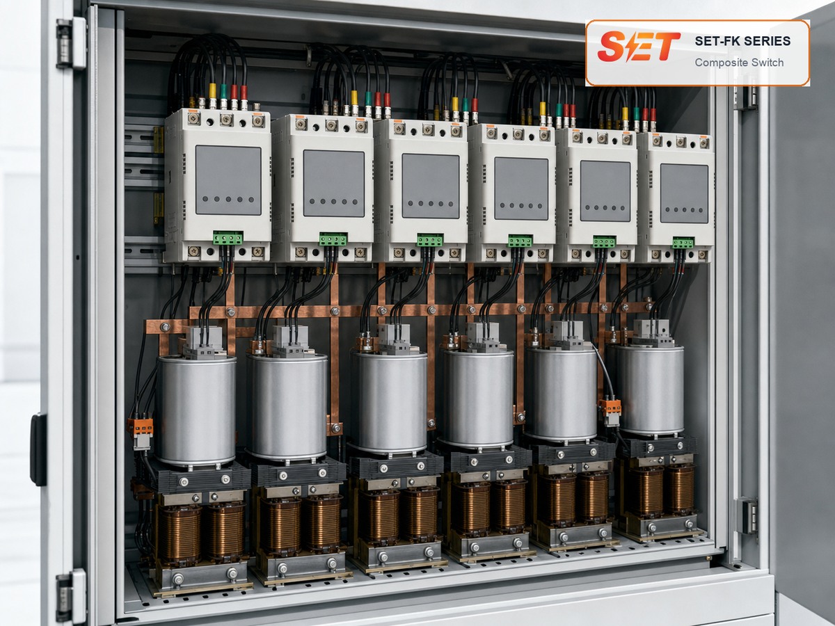
Typical installation in a multi-step low-voltage capacitor compensation cabinet.
| Model | System | Matched capacitor step | Body dimensions | Mounting dimensions |
|---|---|---|---|---|
| SET-FK-3D/20 | Three-phase common compensation | ≤20 kVAR | 110×151×100 mm | 96×126 mm |
| SET-FK-3D/30 | Three-phase common compensation | ≤30 kVAR | 110×151×100 mm | 96×126 mm |
| SET-FK-3D/40 | Three-phase common compensation | ≤40 kVAR | 110×151×100 mm | 96×126 mm |
| SET-FK-3D/50 | Three-phase common compensation | ≤50 kVAR | 110×151×100 mm | 96×126 mm |
| Product type | Three-phase intelligent composite switch |
|---|---|
| Rated operating voltage | AC 380V |
| Rated frequency | 50Hz |
| Control signal | DC 5-12V / 12mA |
| Response time | <100ms |
| Closing method | Zero-voltage closing with automatic optimum-point detection |
| Opening method | Zero-current opening |
| Available capacitor steps | 20, 30, 40 and 50 kVAR |
| Overall dimensions | 110 × 151 × 100 mm |
| Mounting dimensions | 96 × 126 mm |
Send the system voltage, capacitor-step capacity, wiring diagram and controller output. SET engineers will confirm the suitable model and cabinet configuration.