
| EXECUTIVE TAKEAWAYWhen a plant has rapidly changing or uneven three-phase loads, a static var generator can inject the exact compensation current required in real time. The result is better phase balance, steadier voltage, higher power factor, and fewer nuisance trips than fixed-step compensation can provide. |
SVG for three-phase load balancing is designed for industrial plants that rarely have perfectly symmetrical electrical loads. Welding stations may draw heavily on one phase, single-phase auxiliaries may be distributed unevenly, and variable-speed drives can change the current profile every time a motor accelerates or decelerates. The result is three-phase load imbalance: the phase currents and reactive power are no longer equal.
Even a moderate imbalance can increase neutral or negative-sequence current, create extra transformer and cable heating, and cause voltage unbalance at sensitive equipment. Motors are especially vulnerable because negative-sequence voltage produces a reverse-rotating magnetic field. In practice, that means higher temperature, lower efficiency, vibration, and shorter service life.
A plant should investigate SVG technology when it sees one or more of these symptoms:
A static var generator (SVG), also called an advanced static var generator or active power factor correction unit, uses power electronic switches to create a controlled compensation current. A current transformer measures the load current, the controller separates active, reactive, and unbalanced components, and the SVG injects an equal-and-opposite current back into the network.
Unlike a fixed capacitor bank, an SVG does not wait for a capacitor step to switch. It can continuously adjust its output as the load moves. That makes it suitable for plants where the dominant problem is not only average reactive energy, but also fast changes, phase asymmetry, or limited space for multiple capacitor steps.
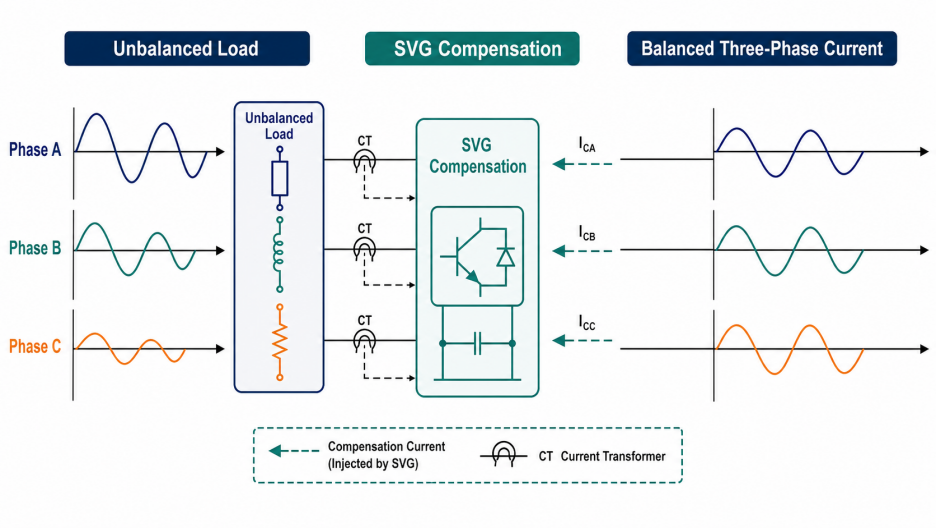
Figure 2. The SVG measures each phase and injects compensation current to balance the three-phase system.
| ENGINEERING PRINCIPLEThe SVG should be sized from the current that must be corrected, not from the connected motor nameplate alone. Measure the real phase currents and reactive demand at the point of connection whenever possible. |
A reliable SVG specification starts with four values: system voltage, nominal frequency, maximum reactive-current demand, and the maximum phase-imbalance current. The required equipment rating should cover the largest simultaneous compensation requirement with a practical engineering margin.
For a three-phase system, the reactive current corresponding to a required kVAR value can be estimated with the familiar relationship:
| CALCULATIONI₍q₎ ≈ Q / (√3 × Vₗₗ) Where I₍q₎ is reactive current in amperes, Q is the required reactive power in VAR, and Vₗₗ is line-to-line voltage in volts. |
For example, a 100 kVAR requirement on a 400 V system corresponds to roughly 144 A of reactive current. If the measured phase imbalance adds another 30 A on the most affected phase, the project should not select a 100 A SVG simply because the average kVAR number looks close. The imbalance current and a margin for future load growth must be included.
Record at least one week of data if the plant has a variable production schedule. Capture phase current, power factor, kW, kVAR, voltage, total harmonic distortion, and the operating state of the largest loads. The most useful data is usually the worst 5-minute or 1-minute interval, not the daily average.
| Project condition | Typical observation | SVG selection implication | Verification |
| Mostly steady motor load | PF drifts slowly | Continuous kVAR correction; moderate dynamic margin | Check 24-hour trend |
| Welding or lifting load | Fast phase-current swings | Prioritize response time and peak current | Capture transient events |
| Uneven single-phase feeders | One phase runs hotter | Add negative/zero-sequence compensation capability | Measure each phase at PCC |
| VFD-dominated plant | Reactive and harmonic current overlap | Confirm SVG and AHF functions are coordinated | Review THDi and resonance risk |
Table 1. Field conditions that affect an SVG specification.
Correct sensing is as important as the SVG power module. The controller must see the current that should be corrected and must not confuse upstream current, downstream current, or parallel equipment current. The preferred measurement point is normally the plant point of common coupling (PCC), where the total load and the compensation current can be evaluated together.
Before handover, compare the SVG display with an independent power-quality analyzer. The phase-current trend should improve when the SVG is enabled, and the equipment should remain within temperature, current, and voltage limits during the fastest load event.
SVG for three-phase load balancing is most valuable when a facility needs fast, continuous correction instead of occasional step switching. Typical applications include manufacturing plants with welding and robotics, CNC machining lines, compressor rooms, cranes and hoists, rolling or forming equipment, HVAC plants, and commercial buildings with uneven single-phase feeders.

Figure 3. Typical SVG application environments: manufacturing, robotics, commercial buildings, and distribution rooms.
Robotic welding, servo drives, and CNC equipment can create rapid changes in reactive current and phase loading. An SVG can respond continuously while the production line changes state, helping the plant avoid voltage dips and reducing the stress placed on transformers and feeders.
Large motors often operate at partial load for long periods, where their power factor is lower. When many motors cycle independently, fixed capacitor steps can overcorrect during light load. An SVG follows the actual demand and can reduce the risk of leading power factor or unnecessary switching.
Commercial buildings may have elevators, air-conditioning drives, lighting power supplies, office equipment, and retail loads on different phases. A properly installed SVG can support phase balancing and reactive-power control without requiring a large bank of fixed steps in every distribution board.
Use the following checklist as a practical handover aid. The exact acceptance limits should be aligned with the project specification, utility requirements, and applicable local standards.
Fixed or switched capacitor banks remain useful where the reactive demand is predictable and the load changes slowly. They can provide economical bulk kVAR support, especially on large steady motors. SVG is a better fit when the correction must be continuous, the load is strongly unbalanced, or the plant experiences rapid transitions.
Many projects use a hybrid architecture: capacitors provide the baseline reactive power and the SVG handles fast correction, phase balancing, and the residual demand that would otherwise force frequent capacitor switching. The correct architecture depends on measured load behavior, harmonic conditions, available space, and the required control response.
| SPECIFICATION TIPDo not specify an SVG from the phrase “improve power factor” alone. Add the required compensation type—reactive, unbalanced, or both—the measurement point, the response expectation, and the maximum current limit to the project schedule. |
Yes, when the selected model and control configuration support the required compensation modes. Confirm whether the project needs three-phase reactive compensation only or also negative-sequence, zero-sequence, and neutral-current compensation.
The required response depends on the load event. Industrial applications with welding, cranes, or fast motor changes generally benefit from millisecond-level response. The final specification should state the response-time definition and test method, not only a marketing phrase.
Not automatically. SVG primarily addresses reactive and unbalanced current. If the plant has significant harmonic current from rectifiers or variable-speed drives, an active harmonic filter or a combined power-quality solution may be required. Measure THDi before deciding.
Provide single-line diagrams, voltage and frequency, CT ratio and location, measured kW/kVAR/PF, phase-current imbalance, harmonic measurements, load profiles, enclosure requirements, ambient conditions, and the required communications protocol. Good data reduces both oversizing and commissioning time.
Three-phase load imbalance is a power-quality problem that is easy to underestimate because the average plant power factor may still look acceptable. When loads change quickly or unevenly, a static var generator gives the control system a continuous way to correct reactive current and phase imbalance at the point where the problem occurs.
The most dependable path is to measure first, size from the worst operating condition, confirm the CT installation, and test the equipment under real production events. For a project-specific recommendation, share your voltage, maximum load current, phase-current readings, target power factor, harmonic data, and installation environment with the Elumotive power-quality team.
Request an SVG sizing review: www.elumotive.com/contact/