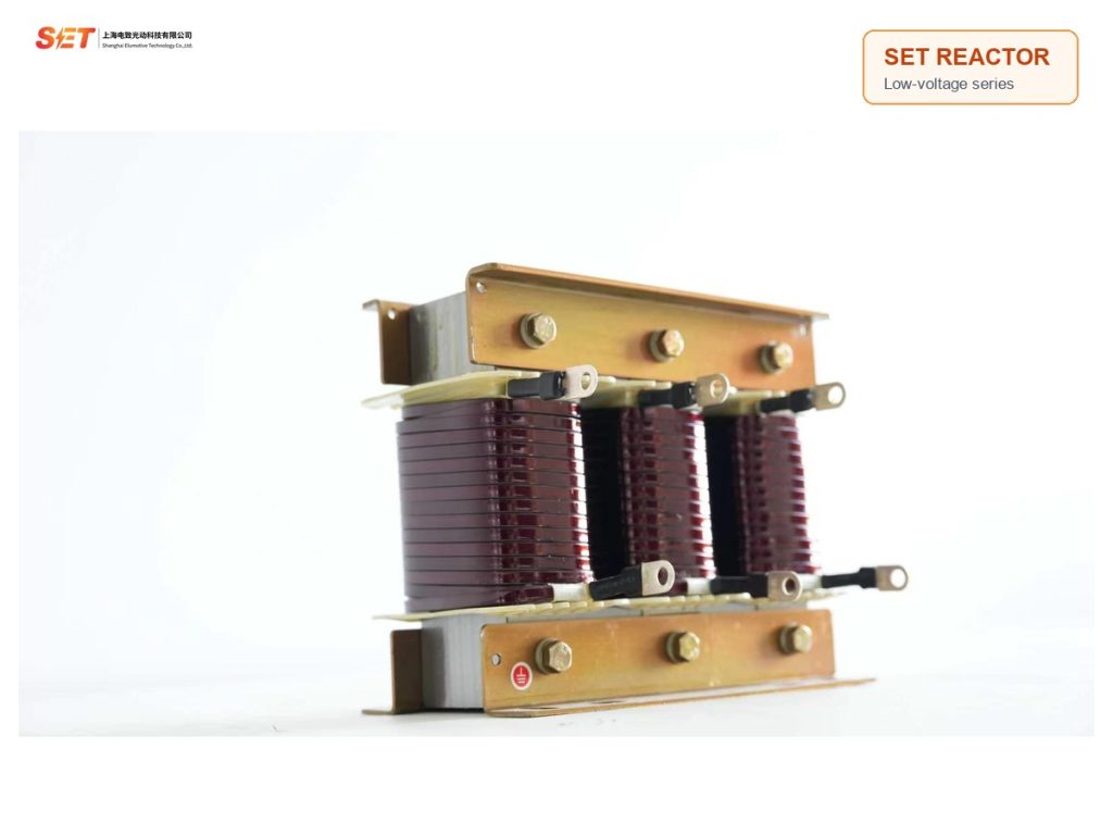
Model: SET-CKDJ
SET-CKDJ split-phase low-voltage series reactor for capacitor banks, 7%/14% reactance, 10-40 kVAR, Class H insulation and ≤45 dB noise.
Split Phase series reactor SET-CKDJ is designed for low-voltage capacitor banks. It connects in series with the capacitor step to limit switching inrush current, reduce resonance risk and improve the operating environment of the compensation cabinet.
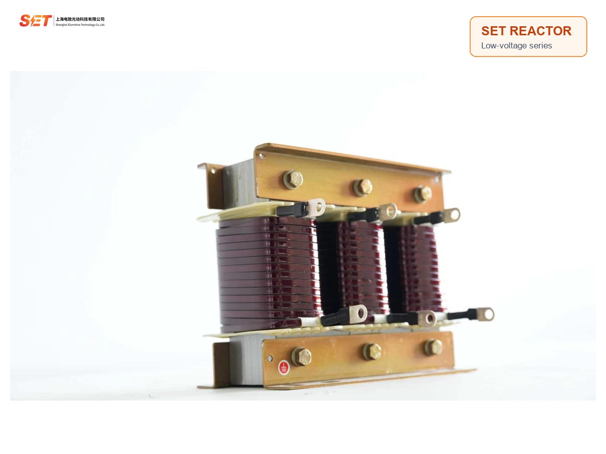
Non-linear loads such as rectifiers and converters inject harmonic current into the low-voltage system. A capacitor bank without coordinated reactance can amplify an unfavorable resonance condition and experience high current, switching stress or premature ageing.
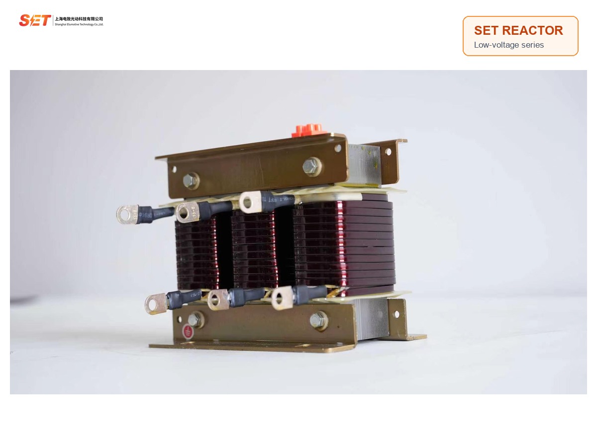
The SET-CKDJ reactor is connected in series with the capacitor step. Its inductive reactance helps control the current path, suppress capacitor energization inrush and reduce operating overvoltage. The reactor and capacitor must therefore be selected as one coordinated branch rather than as independent components.
Cold-rolled silicon-steel laminations are punched and stacked for uniform geometry, controlled losses and stable operation.
Insulated conductors are machine wound for consistent coil shape and reliable electrical performance.
Pre-baking, vacuum impregnation and thermal curing integrate the coil and core to help control vibration, temperature rise and noise.
Clamping parts receive corrosion treatment, while key clamping components use non-magnetic materials.
Compact external dimensions and accessible terminals simplify installation in standard reactive-power compensation cabinets.
The documented continuous operating capability is up to 1.35 times rated current, including fundamental and harmonic components.

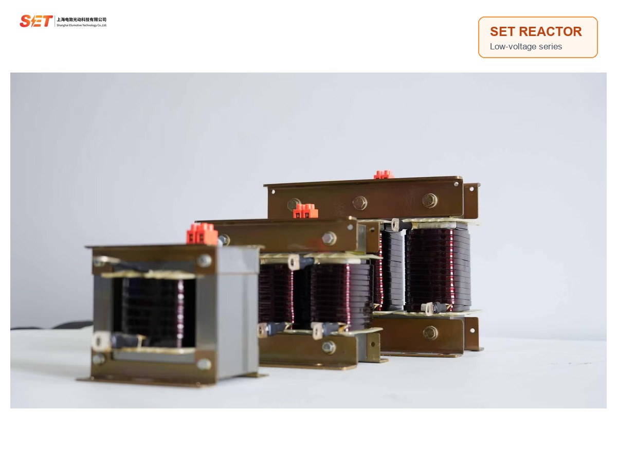
Use the table below for the documented 7% models. Select by compensation configuration, matched capacitor-step rating and cabinet space; final selection must also consider system voltage and the project harmonic study.
| Model | Matched capacitor | Body size (L×D×H, mm) | Mounting size (A×B, mm) |
|---|---|---|---|
| SET-CKDJ-280-0.7-7% | 10 kVAR | 155×145×160 | 80×85 |
| SET-CKDJ-280-1.05-7% | 15 kVAR | 190×145×180 | 80×85 |
| SET-CKDJ-280-1.4-7% | 20 kVAR | 190×155×180 | 80×95 |
| SET-CKDJ-280-1.75-7% | 25 kVAR | 225×150×210 | 120×85 |
| SET-CKDJ-280-2.1-7% | 30 kVAR | 225×160×210 | 120×95 |
| SET-CKDJ-280-2.8-7% | 40 kVAR | 225×180×210 | 120×115 |
The 14% range provides an alternative detuning level for projects that require it. Because reactor ratio changes capacitor branch voltage and current, verify the reactor, capacitor voltage rating and controller strategy together.
| Model | Matched capacitor | Body size (L×D×H, mm) | Mounting size (A×B, mm) |
|---|---|---|---|
| SET-CKDJ-300-1.4-14% | 10 kVAR | 190×165×180 | 80×95 |
| SET-CKDJ-300-2.1-14% | 15 kVAR | 225×150×210 | 120×85 |
| SET-CKDJ-300-2.8-14% | 20 kVAR | 225×170×210 | 120×105 |
| SET-CKDJ-300-3.5-14% | 25 kVAR | 260×175×240 | 135×105 |
| SET-CKDJ-300-4.2-14% | 30 kVAR | 260×175×240 | 135×105 |
| SET-CKDJ-300-5.6-14% | 40 kVAR | 260×195×240 | 135×125 |
| Construction | Dry-type iron-core series reactor |
|---|---|
| System voltage | 230V, 400V or 660V systems |
| Available reactance | 6%, 7%, 12% and 14%; standard selection tables below cover 7% and 14% |
| Ambient temperature | -25°C to +45°C |
| Relative humidity | ≤90% |
| Altitude | ≤2000 m |
| Rated insulation level | 3 kV/min |
| Temperature rise limit | Core ≤85K; coil ≤95K |
| Noise | ≤45 dB |
| Continuous operating current | ≤1.35 × rated current, including fundamental and harmonic components |
| Reactance linearity | ≥0.95 at 1.8 × rated current |
| Phase reactance tolerance | Difference between phases ≤±3% |
| Thermal class | Class H, 180°C |
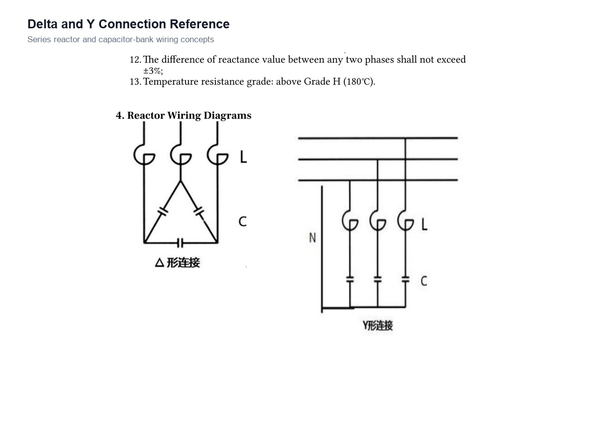
The source manual provides delta and Y connection concepts for series reactor and capacitor branches. The correct arrangement depends on whether the panel uses independent phase capacitor compensation, the selected capacitor voltage and the controller wiring.
Before energizing, verify terminal identification, phase sequence, conductor size, protection and ventilation. Do not use the dimensional table as a substitute for the approved project drawing because custom specifications may change the final body size.
No. The matched capacitor rating is only one input. The system voltage, capacitor rated voltage, reactance ratio, connection method, harmonic spectrum and cabinet ventilation must be checked together.
They represent different reactor-to-capacitor reactance ratios. Use the ratio specified by the system design or harmonic study; changing the ratio without recalculating the capacitor branch can lead to an unsuitable branch voltage or tuning point.
The manual requires good ventilation and states that ventilation equipment should be added when the reactor is installed inside a cabinet. Confirm the final heat dissipation design for the project.
Send the single-line diagram, system voltage, capacitor step kVAR, capacitor rated voltage and harmonic measurement. SET engineers will confirm the reactor model and branch configuration.